
No products in the cart.
-46%On Sale

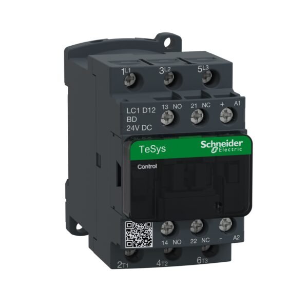
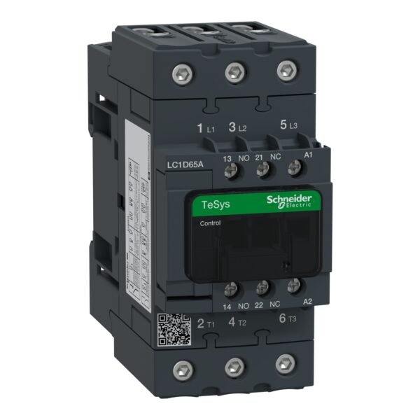
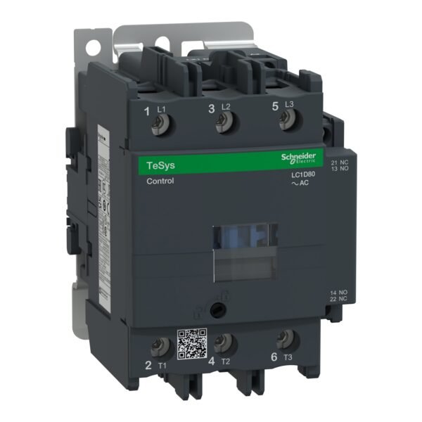
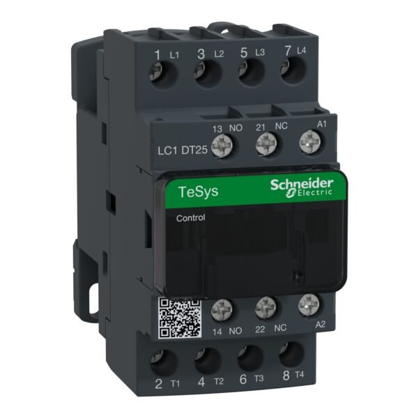
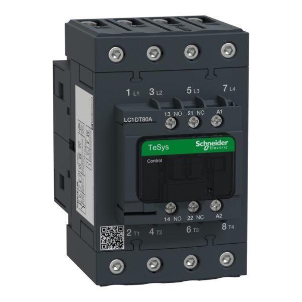
Schneider LC1D12BD Contactor | TeSys D contactor – 3P(3 NO) – AC-3 – <= 440 V 12 A – 24 V DC coil
Schneider LC1D12BD Contactor
Original price was: EGP 4,437.85.EGP 2,401.10Current price is: EGP 2,401.10.
Description
Schneider LC1D12BD Contactor | TeSys D contactor – 3P(3 NO) – AC-3 – <= 440 V 12 A – 24 V DC coil
Schneider LC1D12BD Contactor: Your Ultimate Guide to Reliable Electrical Control
is a vital component in electrical control systems, renowned for its efficiency and reliability. In this comprehensive guide, we delve into the features, applications, installation tips, maintenance guidelines, and more, to provide you with a thorough understanding of this indispensable electrical device.
Understanding the Functionality of Contactors
Contactors are electromechanical switches designed to control the flow of electricity in electrical circuits. They consist of a coil, contacts, and an enclosure. When the coil is energized, it generates a magnetic field, which attracts the contacts, closing the circuit and allowing current to flow. Schneider LC1D12BD Contactor operates on this principle, offering seamless control over electrical loads.
Features of Schneider LC1D12BD Contactor
Coil Voltage
is available in various coil voltage options, catering to different voltage requirements of electrical systems. This versatility ensures compatibility with a wide range of applications.
AC/DC Operation
One of the standout features of the Schneider LC1D12BD Contactor is its capability to operate with both AC and DC voltage, providing flexibility in various electrical setups.
Contact Ratings
With high-quality silver alloy contacts, the Schneider LC1D12BD Contactor ensures reliable performance and durability. It offers excellent contact ratings, making it suitable for demanding industrial environments.
Applications
Schneider LC1D12BD Contactor finds extensive usage in various industries and applications, including:
- Motor control
- Lighting control
- HVAC systems
- Industrial machinery
- Building automation
Advantages
- Robust construction for long-term reliability
- Compact design, saving space in control panels
- Low power consumption, contributing to energy efficiency
- Easy installation and maintenance, reducing downtime
- Wide operating temperature range for versatility in different environments
Installation Guide
Installing the Schneider LC1D12BD Contactor is straightforward, but it requires adherence to safety precautions and proper wiring techniques. Refer to the manufacturer’s instructions and the provided wiring diagram for accurate installation.
Wiring Diagram
Ensure correct wiring connections according to the provided diagram to prevent electrical hazards and ensure optimal performance.
Safety Precautions
- Disconnect power supply before installation or servicing.
- Use appropriate personal protective equipment (PPE).
- Follow local electrical codes and regulations.
Maintenance Tips
Regular maintenance is crucial to ensure the continued efficiency and longevity of the Schneider LC1D12BD Contactor. Here are some maintenance tips:
- Inspect for signs of wear or damage.
- Clean contacts and terminals regularly.
- Check for loose connections and tighten if necessary.
- Lubricate moving parts as recommended by the manufacturer.
Troubleshooting Common Issues
In case of any operational issues, troubleshooting the Schneider LC1D12BD Contactor can help identify and resolve problems promptly. Common issues may include:
- Failure to energize
- Overheating
- Welding of contacts
- Coil failure
Refer to the manufacturer’s troubleshooting guide or consult a qualified technician for assistance.
Comparison with Other Contactors
stands out among its competitors due to its superior quality, reliability, and versatility. However, comparing it with other contactors based on specific requirements can help in making an informed decision.
Additional information
| brands | Schneider Electric |
|---|
Specifications
| Range of product | TeSys Deca |
|---|---|
| Product or component type | Contactor |
| Device short name | LC1D |
| Contactor application | Resistive load Motor control |
| Utilisation category | AC-1 AC-4 AC-3 AC-3e |
| Poles description | 3P |
| [Ue] rated operational voltage | Power circuit: <= 690 V AC 25...400 Hz Power circuit: <= 300 V DC |
| [Ie] rated operational current | 25 A (at <60 °C) at <= 440 V AC AC-1 for power circuit 12 A (at <60 °C) at <= 440 V AC AC-3 for power circuit 12 A (at <60 °C) at <= 440 V AC AC-3e for power circuit |
| [Uc] control circuit voltage | 24 V DC |
| Motor power kW | 3 kW at 220...230 V AC 50/60 Hz (AC-3) 5.5 kW at 380...400 V AC 50/60 Hz (AC-3) 5.5 kW at 415...440 V AC 50/60 Hz (AC-3) 7.5 kW at 500 V AC 50/60 Hz (AC-3) 7.5 kW at 660...690 V AC 50/60 Hz (AC-3) 3.7 kW at 400 V AC 50/60 Hz (AC-4) 3 kW at 220...230 V AC 50/60 Hz (AC-3e) 5.5 kW at 380...400 V AC 50/60 Hz (AC-3e) 5.5 kW at 415...440 V AC 50/60 Hz (AC-3e) 7.5 kW at 500 V AC 50/60 Hz (AC-3e) 7.5 kW at 660...690 V AC 50/60 Hz (AC-3e) |
|---|---|
| Motor power hp | 0.5 hp at 115 V AC 50/60 Hz for 1 phase motors 2 hp at 230/240 V AC 50/60 Hz for 1 phase motors 3 hp at 200/208 V AC 50/60 Hz for 3 phases motors 3 hp at 230/240 V AC 50/60 Hz for 3 phases motors 7.5 hp at 460/480 V AC 50/60 Hz for 3 phases motors 10 hp at 575/600 V AC 50/60 Hz for 3 phases motors |
| Compatibility code | LC1D |
| Pole contact composition | 3 NO |
| Protective cover | With |
| [Ith] conventional free air thermal current | 25 A (at 60 °C) for power circuit 10 A (at 60 °C) for signalling circuit |
| Irms rated making capacity | 250 A at 440 V for power circuit conforming to IEC 60947 140 A AC for signalling circuit conforming to IEC 60947-5-1 250 A DC for signalling circuit conforming to IEC 60947-5-1 |
| Rated breaking capacity | 250 A at 440 V for power circuit conforming to IEC 60947 |
| [Icw] rated short-time withstand current | 105 A 40 °C - 10 s for power circuit 210 A 40 °C - 1 s for power circuit 30 A 40 °C - 10 min for power circuit 61 A 40 °C - 1 min for power circuit 100 A - 1 s for signalling circuit 120 A - 500 ms for signalling circuit 140 A - 100 ms for signalling circuit |
| Associated fuse rating | 10 A gG for signalling circuit conforming to IEC 60947-5-1 40 A gG at <= 690 V coordination type 1 for power circuit 25 A gG at <= 690 V coordination type 2 for power circuit |
| Average impedance | 2.5 mOhm - Ith 25 A 50 Hz for power circuit |
| Power dissipation per pole | 0.36 W AC-3 1.56 W AC-1 0.36 W AC-3e |
| [Ui] rated insulation voltage | Power circuit: 690 V conforming to IEC 60947-4-1 Power circuit: 600 V CSA certified Power circuit: 600 V UL certified Signalling circuit: 690 V conforming to IEC 60947-1 Signalling circuit: 600 V CSA certified Signalling circuit: 600 V UL certified |
| Overvoltage category | III |
| Pollution degree | 3 |
| [Uimp] rated impulse withstand voltage | 6 kV conforming to IEC 60947 |
| Safety reliability level | B10d = 1369863 cycles contactor with nominal load conforming to EN/ISO 13849-1 B10d = 20000000 cycles contactor with mechanical load conforming to EN/ISO 13849-1 |
| Mechanical durability | 30 Mcycles |
| Electrical durability | 2 Mcycles 12 A AC-3 at Ue <= 440 V 0.8 Mcycles 25 A AC-1 at Ue <= 440 V 2 Mcycles 12 A AC-3e at Ue <= 440 V |
| Control circuit type | DC standard |
| Coil technology | With integral suppression device |
| Control circuit voltage limits | 0.1...0.25 Uc (-40…70 °C):drop-out DC 0.7...1.25 Uc (-40…60 °C):operational DC 1...1.25 Uc (60…70 °C):operational DC |
| Inrush power in W | 5.4 W (at 20 °C) |
| Hold-in power consumption in W | 5.4 W at 20 °C |
| Operating time | 63 ±15 % ms closing 20 ±20 % ms opening |
| Time constant | 28 ms |
| Maximum operating rate | 3600 cyc/h 60 °C |
| Maximum operating rate | 3600 cyc/h at 60 °C |
| Connections - terminals | Power circuit: screw clamp terminals 1 1…4 mm² - cable stiffness: flexible without cable end Power circuit: screw clamp terminals 2 1…4 mm² - cable stiffness: flexible without cable end Power circuit: screw clamp terminals 1 1…4 mm² - cable stiffness: flexible with cable end Power circuit: screw clamp terminals 2 1…2.5 mm² - cable stiffness: flexible with cable end Power circuit: screw clamp terminals 1 1…4 mm² - cable stiffness: solid without cable end Power circuit: screw clamp terminals 2 1…4 mm² - cable stiffness: solid without cable end Control circuit: screw clamp terminals 1 1…4 mm² - cable stiffness: flexible without cable end Control circuit: screw clamp terminals 2 1…4 mm² - cable stiffness: flexible without cable end Control circuit: screw clamp terminals 1 1…4 mm² - cable stiffness: flexible with cable end Control circuit: screw clamp terminals 2 1…2.5 mm² - cable stiffness: flexible with cable end Control circuit: screw clamp terminals 1 1…4 mm² - cable stiffness: solid without cable end Control circuit: screw clamp terminals 2 1…4 mm² - cable stiffness: solid without cable end |
| Tightening torque | Power circuit: 1.7 N.m - on screw clamp terminals - with screwdriver flat Ø 6 mm Power circuit: 1.7 N.m - on screw clamp terminals - with screwdriver Philips No 2 Control circuit: 1.7 N.m - on screw clamp terminals - with screwdriver flat Ø 6 mm Control circuit: 1.7 N.m - on screw clamp terminals - with screwdriver Philips No 2 Control circuit: 1.7 N.m - on screw clamp terminals - with screwdriver pozidriv No 2 Power circuit: 1.7 N.m - on screw clamp terminals - with screwdriver pozidriv No 2 |
| Auxiliary contact composition | 1 NO + 1 NC |
| Auxiliary contacts type | type mechanically linked 1 NO + 1 NC conforming to IEC 60947-5-1 type mirror contact 1 NC conforming to IEC 60947-4-1 |
| Signalling circuit frequency | 25...400 Hz |
| Minimum switching voltage | 17 V for signalling circuit |
| Minimum switching current | 5 mA for signalling circuit |
| Insulation resistance | > 10 MOhm for signalling circuit |
| Non-overlap time | 1.5 ms on de-energisation between NC and NO contact 1.5 ms on energisation between NC and NO contact |
| Mounting support | Plate Rail |
| Standards | CSA C22.2 No 14 EN 60947-4-1 EN 60947-5-1 IEC 60947-4-1 IEC 60947-5-1 UL 60947-4-1 IEC 60335-1:Clause 30.2 IEC 60335-2-40:Annex JJ UL 60335-2-40:Annex JJ CSA C22.2 No 60947-4-1 |
|---|---|
| Product certifications | UL CCC CSA Marine UKCA EAC CB Scheme |
| IP degree of protection | IP20 front face conforming to IEC 60529 |
| Protective treatment | TH conforming to IEC 60068-2-30 |
| Climatic withstand | conforming to IACS E10 exposure to damp heat conforming to IEC 60947-1 Annex Q category D exposure to damp heat |
| Permissible ambient air temperature around the device | -40…60 °C 60…70 °C with derating |
| Operating altitude | 0...3000 m |
| Fire resistance | 850 °C conforming to IEC 60695-2-1 |
| Flame retardance | V1 conforming to UL 94 |
| Mechanical robustness | Vibrations contactor open (2 Gn, 5...300 Hz) Vibrations contactor closed (4 Gn, 5...300 Hz) Shocks contactor open (10 Gn for 11 ms) Shocks contactor closed (15 Gn for 11 ms) |
| Height | 77 mm |
| Width | 45 mm |
| Depth | 95 mm |
| Net weight | 0.485 kg |
| Unit Type of Package 1 | PCE |
|---|---|
| Number of Units in Package 1 | 1 |
| Package 1 Height | 5.000 cm |
| Package 1 Width | 9.000 cm |
| Package 1 Length | 11.000 cm |
| Package 1 Weight | 520.300 g |
| Unit Type of Package 2 | S02 |
| Number of Units in Package 2 | 15 |
| Package 2 Height | 15.000 cm |
| Package 2 Width | 30.000 cm |
| Package 2 Length | 40.000 cm |
| Package 2 Weight | 8.078 kg |
| Unit Type of Package 3 | P06 |
| Number of Units in Package 3 | 240 |
| Package 3 Height | 75.000 cm |
| Package 3 Width | 60.000 cm |
| Package 3 Length | 80.000 cm |
| Package 3 Weight | 136.620 kg |
| Warranty | 18 months |
|---|


Reviews
There are no reviews yet.