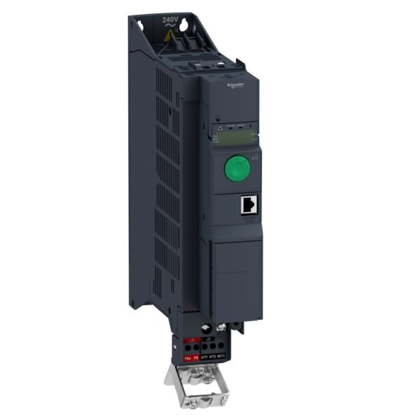
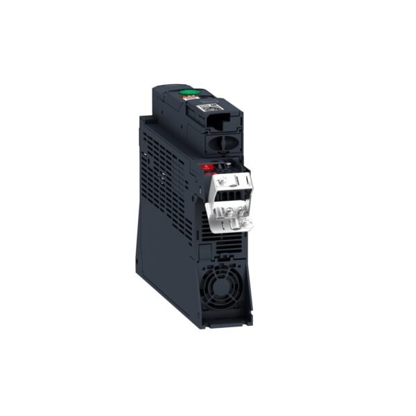
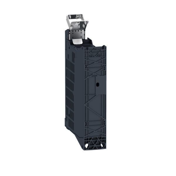
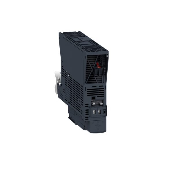
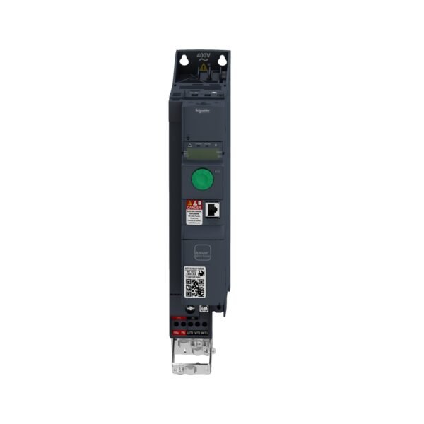
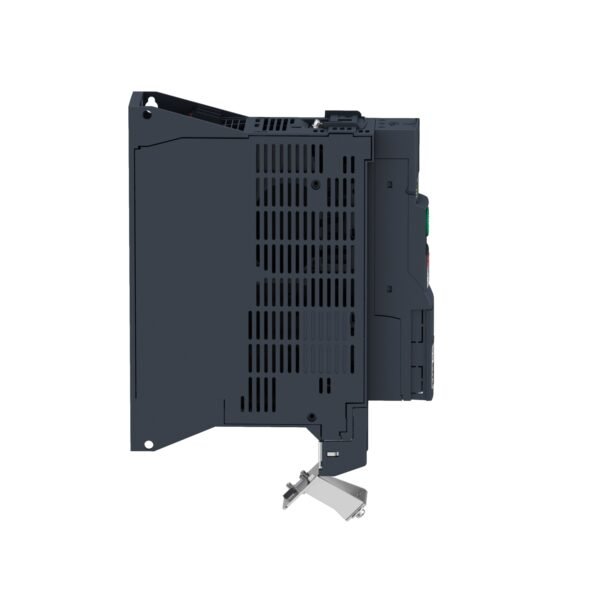
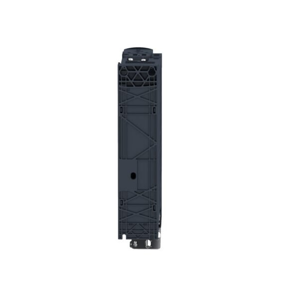
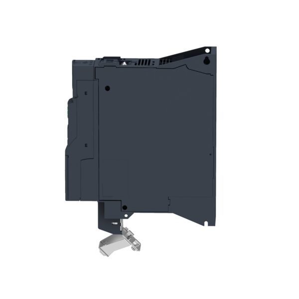
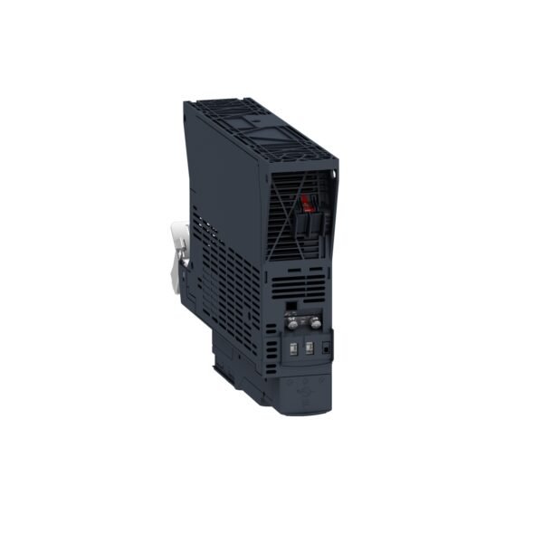
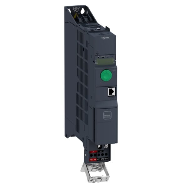
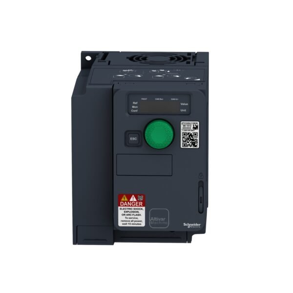
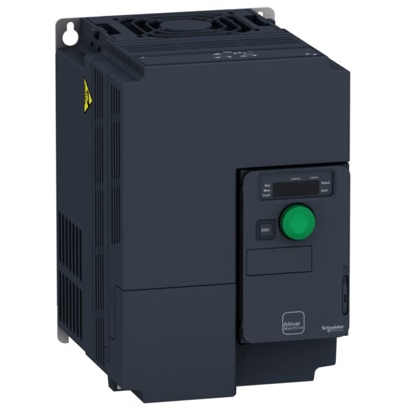
Schneider ATV320U40N4B | Variable speed drive, ATV320, 4 kW, 380…500 V, 3 phases, book
Description
Introduction
Variable speed drives play a crucial role in modern industrial processes by controlling the speed and torque of electric motors. The Schneider ATV320U40N4B is a reliable and efficient solution for achieving optimal performance and energy savings.
Features
it comes equipped with advanced features such as:
- Power Rating: 4 kW
- Voltage Range: 380V to 500V, 3 phases
- Compact Design: Space-saving and easy to install
- Integrated Functions: Built-in safety and protection features
- Communication Options: Connectivity for monitoring and control
- Energy Efficiency: Optimized for reduced power consumption
Applications
This variable speed drive is widely used in various industries including:
- Manufacturing
- HVAC (Heating, Ventilation, and Air Conditioning)
- Water and wastewater treatment
- Renewable energy systems
- Conveyor systems
- Pumping applications
Advantages
it offers several advantages:
- Energy Savings: Efficient motor control leads to reduced energy consumption.
- Precision Control: Adjustable speed settings for different operational needs.
- Maintenance Cost Reduction: Improved motor performance prolongs equipment lifespan.
- Compliance: Meets industry standards for safety and reliability.
Installation
Installing it follows these basic steps:
- Preparation: Ensure power supply compatibility and safety precautions.
- Mounting: Securely install the drive in a suitable location.
- Wiring: Connect power and control cables according to the manual.
- Configuration: Set parameters for motor type and operating conditions.
Maintenance
To maintain optimal performance:
- Regularly check for signs of wear or damage.
- Monitor motor temperature and operating parameters.
- Follow recommended service intervals and cleaning procedures.
Troubleshooting
Common issues with variable speed drives include:
- Overheating: Check ventilation and cooling systems.
- Voltage Fluctuations: Verify input power quality.
- Error Codes: Refer to the manual for troubleshooting steps.
Comparison
Compared to similar products in the market, the ATV320U40N4B stands out for its:
- Compact size and easy integration.
- Comprehensive safety features.
- Energy-efficient operation.
- User-friendly interface for configuration and monitoring.
Customer Reviews
Users of the ATV320U40N4B have praised its reliability, performance, and ease of use. Feedback often highlights:
- Smooth motor control and speed adjustments.
- Cost savings due to reduced energy consumption.
- Long-term durability and minimal maintenance requirements.
Conclusion
The Schneider ATV320U40N4B variable speed drive is a top choice for industries seeking efficient motor control solutions. Its advanced features, ease of installation, and cost-saving benefits make it a valuable asset for optimizing industrial processes and reducing operational expenses.
Additional information
| brands | Schneider Electric |
|---|
Specifications
| Range of product | Altivar Machine ATV320 |
|---|---|
| Product or component type | Variable speed drive |
| Product specific application | Complex machines |
| Variant | Standard version |
| Format of the drive | Book |
| Mounting mode | Cabinet mount |
| Communication port protocol | Modbus serial CANopen |
| Option card | Communication module, CANopen Communication module, EtherCAT Communication module, Profibus DP V1 Communication module, PROFINET Communication module, Ethernet Powerlink Communication module, EtherNet/IP Communication module, DeviceNet |
| [Us] rated supply voltage | 380...500 V - 15...10 % |
| Nominal output current | 9.5 A |
| Motor power kW | 4.0 kW for heavy duty |
| EMC filter | Class C2 EMC filter integrated |
| IP degree of protection | IP20 |
| Discrete input number | 7 |
|---|---|
| Discrete input type | STO safe torque off, 24 V DC, impedance: 1.5 kOhm DI1...DI6 logic inputs, 24 V DC (30 V) DI5 programmable as pulse input: 0…30 kHz, 24 V DC (30 V) |
| Discrete input logic | Positive logic (source) Negative logic (sink) |
| Discrete output number | 3 |
| Discrete output type | Open collector DQ+ 0…1 kHz 30 V DC 100 mA Open collector DQ- 0…1 kHz 30 V DC 100 mA |
| Analogue input number | 3 |
| Analogue input type | AI1 voltage: 0...10 V DC, impedance: 30 kOhm, resolution 10 bits AI2 bipolar differential voltage: +/- 10 V DC, impedance: 30 kOhm, resolution 10 bits AI3 current: 0...20 mA (or 4-20 mA, x-20 mA, 20-x mA or other patterns by configuration), impedance: 250 Ohm, resolution 10 bits |
| Analogue output number | 1 |
| Analogue output type | Software-configurable current AQ1: 0...20 mA impedance 800 Ohm, resolution 10 bits Software-configurable voltage AQ1: 0...10 V DC impedance 470 Ohm, resolution 10 bits |
| Relay output type | Configurable relay logic R1A 1 NO electrical durability 100000 cycles Configurable relay logic R1B 1 NC electrical durability 100000 cycles Configurable relay logic R1C Configurable relay logic R2A 1 NO electrical durability 100000 cycles Configurable relay logic R2C |
| Maximum switching current | Relay output R1A, R1B, R1C on resistive load, cos phi = 1: 3 A at 250 V AC Relay output R1A, R1B, R1C on resistive load, cos phi = 1: 3 A at 30 V DC Relay output R1A, R1B, R1C, R2A, R2C on inductive load, cos phi = 0.4 and L/R = 7 ms: 2 A at 250 V AC Relay output R1A, R1B, R1C, R2A, R2C on inductive load, cos phi = 0.4 and L/R = 7 ms: 2 A at 30 V DC Relay output R2A, R2C on resistive load, cos phi = 1: 5 A at 250 V AC Relay output R2A, R2C on resistive load, cos phi = 1: 5 A at 30 V DC |
| Minimum switching current | Relay output R1A, R1B, R1C, R2A, R2C: 5 mA at 24 V DC |
| Method of access | Slave CANopen |
| 4 quadrant operation possible | True |
| Asynchronous motor control profile | Voltage/frequency ratio, 5 points Flux vector control without sensor, standard Voltage/frequency ratio - Energy Saving, quadratic U/f Flux vector control without sensor - Energy Saving Voltage/frequency ratio, 2 points |
| Synchronous motor control profile | Vector control without sensor |
| Maximum output frequency | 0.599 kHz |
| Acceleration and deceleration ramps | Linear U S CUS Ramp switching Acceleration/deceleration ramp adaptation Acceleration/deceleration automatic stop with DC injection |
| Motor slip compensation | Automatic whatever the load Adjustable 0...300 % Not available in voltage/frequency ratio (2 or 5 points) |
| Switching frequency | 2...16 kHz adjustable 4...16 kHz with derating factor |
| Nominal switching frequency | 4 kHz |
| Braking to standstill | By DC injection |
| Brake chopper integrated | True |
| Line current | 13.7 A at 380 V (heavy duty) 10.5 A at 500 V (heavy duty) |
| Maximum input current | 13.7 A |
| Maximum output voltage | 500 V |
| Apparent power | 9.1 kVA at 500 V (heavy duty) |
| Network frequency | 50...60 Hz |
| Relative symmetric network frequency tolerance | 5 % |
| Prospective line Isc | 5 kA |
| Base load current at high overload | 9.5 A |
| Power dissipation in W | Fan: 111 W at 380 V, switching frequency 4 kHz |
| With safety function Safely Limited Speed (SLS) | True |
| With safety function Safe brake management (SBC/SBT) | False |
| With safety function Safe Operating Stop (SOS) | False |
| With safety function Safe Position (SP) | False |
| With safety function Safe programmable logic | False |
| With safety function Safe Speed Monitor (SSM) | False |
| With safety function Safe Stop 1 (SS1) | True |
| With sft fct Safe Stop 2 (SS2) | False |
| With safety function Safe torque off (STO) | True |
| With safety function Safely Limited Position (SLP) | False |
| With safety function Safe Direction (SDI) | False |
| Protection type | Input phase breaks: drive Overcurrent between output phases and earth: drive Overheating protection: drive Short-circuit between motor phases: drive Thermal protection: drive |
| Width | 60 mm |
| Height | 325.0 mm |
| Depth | 245.0 mm |
| Net weight | 3.0 kg |
| Transient overtorque | 170…200 % of nominal motor torque |
| Operating position | Vertical +/- 10 degree |
|---|---|
| Product certifications | CE ATEX NOM GOST EAC RCM KC |
| Marking | CE ATEX UL CSA EAC RCM |
| Standards | IEC 61800-5-1 |
| Electromagnetic compatibility | Electrostatic discharge immunity test level 3 conforming to IEC 61000-4-2 Radiated radio-frequency electromagnetic field immunity test level 3 conforming to IEC 61000-4-3 Electrical fast transient/burst immunity test level 4 conforming to IEC 61000-4-4 1.2/50 µs - 8/20 µs surge immunity test level 3 conforming to IEC 61000-4-5 Conducted radio-frequency immunity test level 3 conforming to IEC 61000-4-6 Voltage dips and interruptions immunity test conforming to IEC 61000-4-11 |
| Environmental class (during operation) | Class 3C3 according to IEC 60721-3-3 Class 3S2 according to IEC 60721-3-3 |
| Maximum acceleration under shock impact (during operation) | 150 m/s² at 11 ms |
| Maximum acceleration under vibrational stress (during operation) | 10 m/s² at 13...200 Hz |
| Maximum deflection under vibratory load (during operation) | 1.5 mm at 2...13 Hz |
| Permitted relative humidity (during operation) | Class 3K5 according to EN 60721-3 |
| Volume of cooling air | 11.3 m3/h |
| Overvoltage category | III |
| Regulation loop | Adjustable PID regulator |
| Speed accuracy | +/- 10 % of nominal slip 0.2 Tn to Tn |
| pollution degree | 2 |
| Ambient air transport temperature | -25…70 °C |
| Ambient air temperature for operation | -10…50 °C without derating 50…60 °C with derating factor |
| Ambient air temperature for storage | -25…70 °C |
| Unit Type of Package 1 | PCE |
|---|---|
| Number of Units in Package 1 | 1 |
| Package 1 Height | 9.600 cm |
| Package 1 Width | 27.500 cm |
| Package 1 Length | 32.500 cm |
| Package 1 Weight | 2.843 kg |
| Unit Type of Package 2 | S06 |
| Number of Units in Package 2 | 20 |
| Package 2 Height | 75.000 cm |
| Package 2 Width | 60.000 cm |
| Package 2 Length | 80.000 cm |
| Package 2 Weight | 71.260 kg |
Reviews
There are no reviews yet.