
No products in the cart.
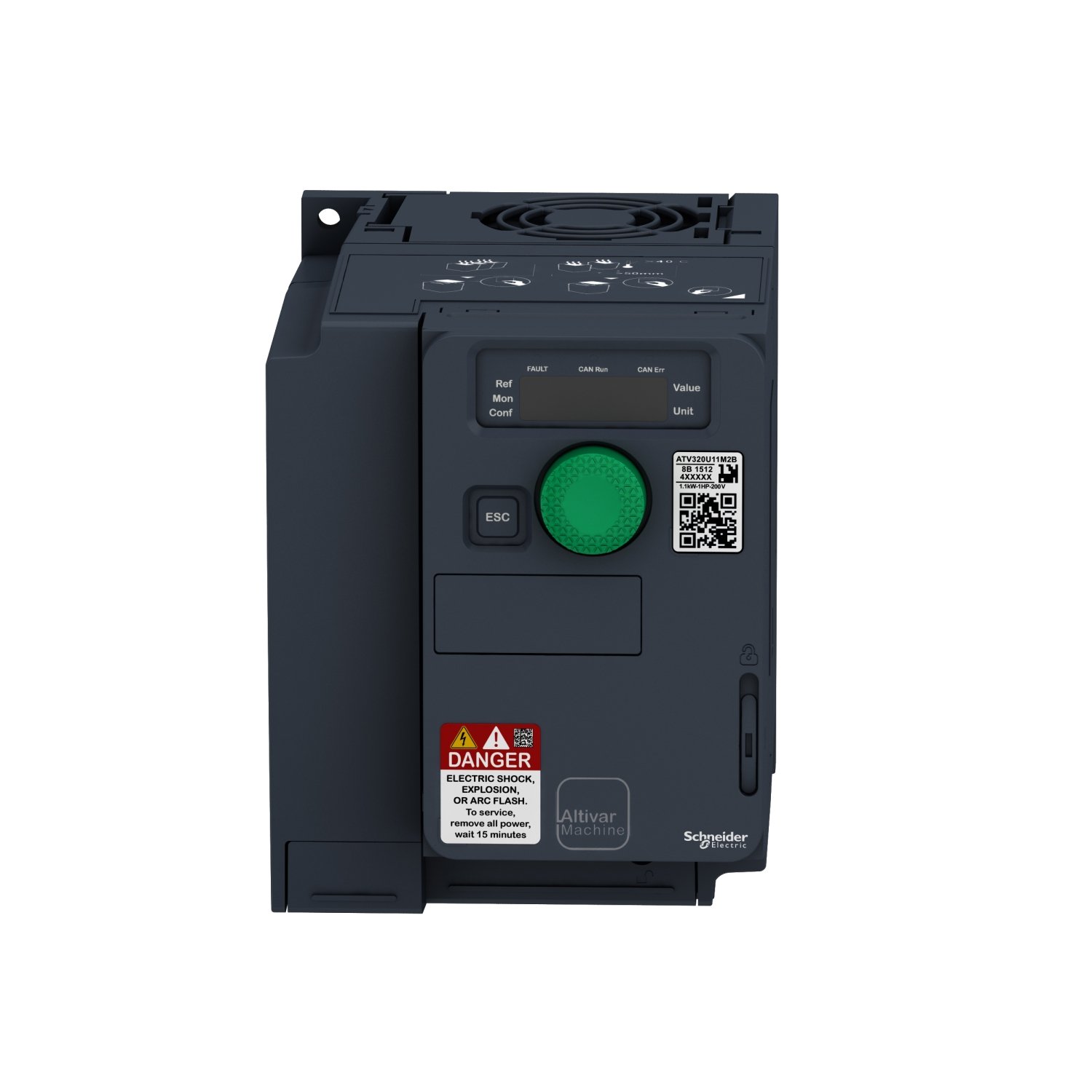


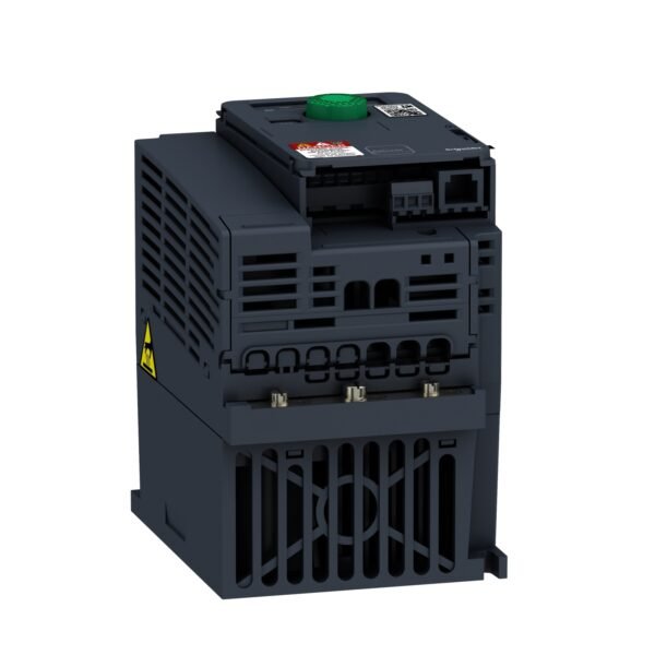


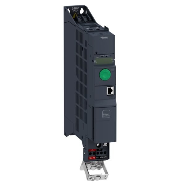
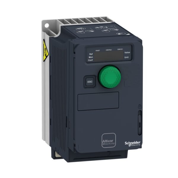
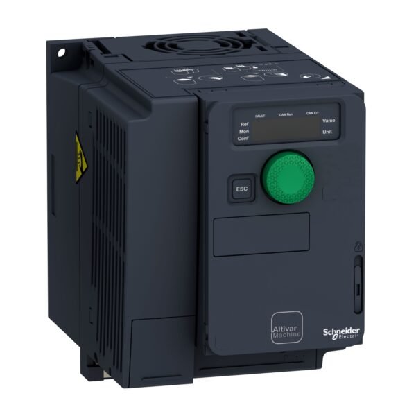
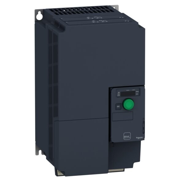
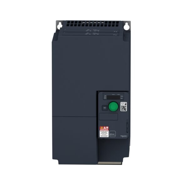
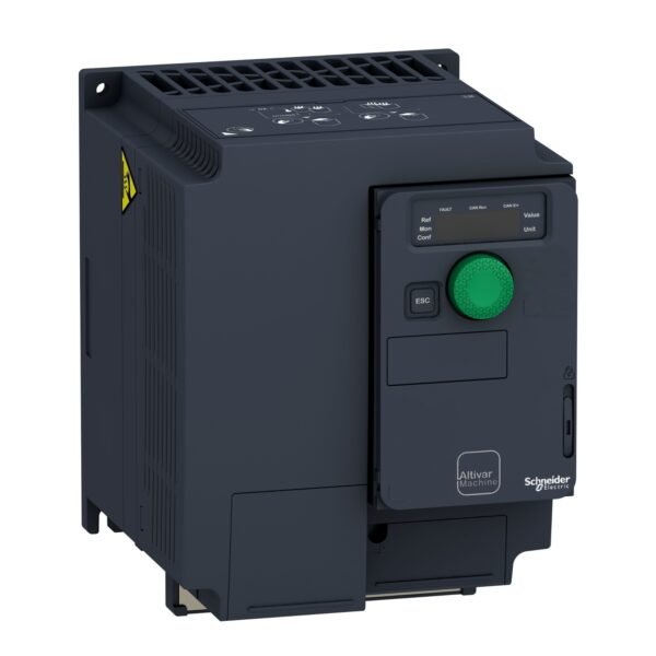
Schneider ATV320U15M2C ATV | Variable speed drive, ATV320, 1.5 kW, 200…240 V, 1 phase, compact
Schneider ATV320U15M2C ATV | Variable speed drive, ATV320, 1.5 kW, 200…240 V, 1 phase, compact
EGP 27,645.00
Description
Schneider ATV320U15M2C ATV: Revolutionizing Industrial Automation
In the realm of industrial automation, it stands out as a beacon of innovation and efficiency. Designed to meet the diverse needs of modern industries, this advanced variable frequency drive offers unparalleled performance, reliability, and control. Let’s delve deeper into what makes it a game-changer in the field of automation.
Introduction to Schneider ATV320U15M2C ATV
it is a cutting-edge variable frequency drive (VFD) manufactured by Schneider Electric. Engineered to deliver precise control over motor speed and torque, it plays a crucial role in optimizing the operation of various industrial machinery and equipment. Whether it’s controlling pumps, fans, conveyors, or other motor-driven systems,it offers unmatched flexibility and performance.
Importance
In today’s fast-paced industrial landscape, maximizing efficiency and productivity is paramount. it helps businesses achieve these goals by providing accurate speed and torque control, reducing energy consumption, and minimizing downtime. Its versatility makes it suitable for a wide range of applications across industries such as manufacturing, HVAC, water treatment, and more.
Features
Power and Performance
it boasts impressive power ratings and performance capabilities, allowing it to handle demanding industrial tasks with ease. With its advanced motor control algorithms and high-speed processing capabilities, it ensures smooth operation and precise control over motor speed and torque.
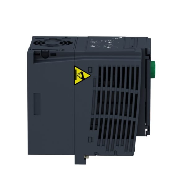
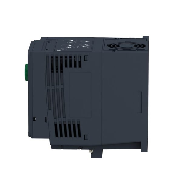
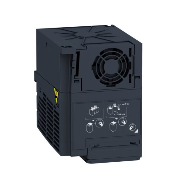
Compact Design and Easy Installation
Despite its powerful performance, it features a compact and space-saving design, making it easy to integrate into existing control systems. Its user-friendly interface and intuitive setup wizard simplify the installation process, reducing downtime and installation costs.
Advanced Control and Monitoring Capabilities
Equipped with advanced control and monitoring features, it provides operators with real-time insights into motor performance and system status. From adjustable acceleration and deceleration ramps to built-in diagnostics and fault logging, it empowers users to optimize system performance and troubleshoot issues quickly.
Applications
The versatility of it makes it suitable for a wide range of industrial applications, including:
- Industrial automation
- Pump and fan control
- HVAC systems
- Conveyor systems
- Water and wastewater treatment
Benefits of Using
Energy Efficiency
By precisely controlling motor speed and torque, it helps reduce energy consumption and operating costs, leading to significant savings for businesses.
Enhanced Productivity
With its reliable performance and advanced control capabilities,it helps optimize production processes, improve throughput, and maximize overall productivity.
Reduced Maintenance Costs
The robust design and built-in diagnostics of it minimize downtime and maintenance costs, ensuring uninterrupted operation and prolonged equipment lifespan.
How to Install and Set Up Schneider ATV320U15M2C ATV
Installation Process
Installing it is a straightforward process that involves mounting the drive, connecting power and motor cables, and configuring basic settings using the intuitive setup wizard.
Configuration Steps
Once installed, users can configure it to suit their specific application requirements, adjusting parameters such as motor speed, acceleration/deceleration rates, and control modes.
Tips for Optimal Performance
To ensure optimal performance and longevity of it, it’s essential to follow recommended maintenance practices and periodically check for any signs of wear or malfunction.
Maintenance and Troubleshooting
Regular Maintenance Practices
Routine maintenance tasks for it include checking for loose connections, inspecting cooling fans and filters, and monitoring motor performance for any abnormalities.
Common Troubleshooting Issues and Solutions
In the event of a fault or malfunction, it provides detailed fault codes and diagnostics to aid in troubleshooting. Common issues such as overvoltage, overcurrent, and motor overheating can often be resolved quickly with the help of these built-in features.
Additional information
| brands | Schneider Electric |
|---|
Specifications
| range of product | Altivar Machine ATV320 |
|---|---|
| product or component type | Variable speed drive |
| Product specific application | Complex machines |
| Variant | Standard version |
| Format of the drive | Compact |
| mounting mode | Wall mount |
| communication port protocol | Modbus serial CANopen |
| Option card | Communication module, CANopen Communication module, EtherCAT Communication module, Profibus DP V1 Communication module, PROFINET Communication module, Ethernet Powerlink Communication module, EtherNet/IP Communication module, DeviceNet |
| [Us] rated supply voltage | 200...240 V - 15...10 % |
| Nominal output current | 8.0 A |
| Motor power kW | 1.5 kW for heavy duty |
| EMC filter | Class C2 EMC filter integrated |
| IP degree of protection | IP20 |
| Discrete input number | 7 |
|---|---|
| Discrete input type | STO safe torque off, 24 V DC, impedance: 1.5 kOhm DI1...DI6 logic inputs, 24 V DC (30 V) DI5 programmable as pulse input: 0…30 kHz, 24 V DC (30 V) |
| Discrete input logic | Positive logic (source) Negative logic (sink) |
| Discrete output number | 3 |
| Discrete output type | Open collector DQ+ 0…1 kHz 30 V DC 100 mA Open collector DQ- 0…1 kHz 30 V DC 100 mA |
| Analogue input number | 3 |
| Analogue input type | AI1 voltage: 0...10 V DC, impedance: 30 kOhm, resolution 10 bits AI2 bipolar differential voltage: +/- 10 V DC, impedance: 30 kOhm, resolution 10 bits AI3 current: 0...20 mA (or 4-20 mA, x-20 mA, 20-x mA or other patterns by configuration), impedance: 250 Ohm, resolution 10 bits |
| Analogue output number | 1 |
| Analogue output type | Software-configurable current AQ1: 0...20 mA impedance 800 Ohm, resolution 10 bits Software-configurable voltage AQ1: 0...10 V DC impedance 470 Ohm, resolution 10 bits |
| Relay output type | Configurable relay logic R1A 1 NO electrical durability 100000 cycles Configurable relay logic R1B 1 NC electrical durability 100000 cycles Configurable relay logic R1C Configurable relay logic R2A 1 NO electrical durability 100000 cycles Configurable relay logic R2C |
| Maximum switching current | Relay output R1A, R1B, R1C on resistive load, cos phi = 1: 3 A at 250 V AC Relay output R1A, R1B, R1C on resistive load, cos phi = 1: 3 A at 30 V DC Relay output R1A, R1B, R1C, R2A, R2C on inductive load, cos phi = 0.4 and L/R = 7 ms: 2 A at 250 V AC Relay output R1A, R1B, R1C, R2A, R2C on inductive load, cos phi = 0.4 and L/R = 7 ms: 2 A at 30 V DC Relay output R2A, R2C on resistive load, cos phi = 1: 5 A at 250 V AC Relay output R2A, R2C on resistive load, cos phi = 1: 5 A at 30 V DC |
| Minimum switching current | Relay output R1A, R1B, R1C, R2A, R2C: 5 mA at 24 V DC |
| Method of access | Slave CANopen |
| 4 quadrant operation possible | True |
| Asynchronous motor control profile | Voltage/frequency ratio, 5 points Flux vector control without sensor, standard Voltage/frequency ratio - Energy Saving, quadratic U/f Flux vector control without sensor - Energy Saving Voltage/frequency ratio, 2 points |
| Synchronous motor control profile | Vector control without sensor |
| Transient overtorque | 170…200 % of nominal motor torque |
| Maximum output frequency | 0.599 kHz |
| Acceleration and deceleration ramps | Linear U S CUS Ramp switching Acceleration/deceleration ramp adaptation Acceleration/deceleration automatic stop with DC injection |
| Motor slip compensation | Automatic whatever the load Adjustable 0...300 % Not available in voltage/frequency ratio (2 or 5 points) |
| Switching frequency | 2...16 kHz adjustable 4...16 kHz with derating factor |
| Nominal switching frequency | 4 kHz |
| Braking to standstill | By DC injection |
| Brake chopper integrated | True |
| Line current | 17.8 A at 200 V (heavy duty) 14.9 A at 240 V (heavy duty) |
| Maximum input current | 17.8 A |
| Maximum output voltage | 240 V |
| Apparent power | 3.6 kVA at 240 V (heavy duty) |
| Network frequency | 50...60 Hz |
| Relative symmetric network frequency tolerance | 5 % |
| Prospective line Isc | 1 kA |
| Base load current at high overload | 4.8 A |
| Power dissipation in W | Fan: 76.0 W at 200 V, switching frequency 4 kHz |
| With safety function Safely Limited Speed (SLS) | True |
| With safety function Safe brake management (SBC/SBT) | False |
| With safety function Safe Operating Stop (SOS) | False |
| With safety function Safe Position (SP) | False |
| With safety function Safe programmable logic | False |
| With safety function Safe Speed Monitor (SSM) | False |
| With safety function Safe Stop 1 (SS1) | True |
| With sft fct Safe Stop 2 (SS2) | False |
| With safety function Safe torque off (STO) | True |
| With safety function Safely Limited Position (SLP) | False |
| With safety function Safe Direction (SDI) | False |
| Protection type | Input phase breaks: drive Overcurrent between output phases and earth: drive Overheating protection: drive Short-circuit between motor phases: drive Thermal protection: drive |
| Width | 105.0 mm |
| Height | 142.0 mm |
| Depth | 158.0 mm |
| net weight | 1.6 kg |
| Operating position | Vertical +/- 10 degree |
|---|---|
| Product certifications | CE ATEX NOM GOST EAC RCM KC |
| marking | CE ATEX UL CSA EAC RCM |
| Standards | IEC 61800-5-1 |
| Electromagnetic compatibility | Electrostatic discharge immunity test level 3 conforming to IEC 61000-4-2 Radiated radio-frequency electromagnetic field immunity test level 3 conforming to IEC 61000-4-3 Electrical fast transient/burst immunity test level 4 conforming to IEC 61000-4-4 1.2/50 µs - 8/20 µs surge immunity test level 3 conforming to IEC 61000-4-5 Conducted radio-frequency immunity test level 3 conforming to IEC 61000-4-6 Voltage dips and interruptions immunity test conforming to IEC 61000-4-11 |
| Environmental class (during operation) | Class 3C3 according to IEC 60721-3-3 Class 3S2 according to IEC 60721-3-3 |
| Maximum acceleration under shock impact (during operation) | 150 m/s² at 11 ms |
| Maximum acceleration under vibrational stress (during operation) | 10 m/s² at 13...200 Hz |
| Maximum deflection under vibratory load (during operation) | 1.5 mm at 2...13 Hz |
| Permitted relative humidity (during operation) | Class 3K5 according to EN 60721-3 |
| Volume of cooling air | 16.0 m3/h |
| Overvoltage category | III |
| Regulation loop | Adjustable PID regulator |
| Speed accuracy | +/- 10 % of nominal slip 0.2 Tn to Tn |
| Pollution degree | 2 |
| Ambient air transport temperature | -25…70 °C |
| Ambient air temperature for operation | -10…50 °C without derating 50…60 °C with derating factor |
| Ambient air temperature for storage | -25…70 °C |
| Unit Type of Package 1 | PCE |
|---|---|
| Number of Units in Package 1 | 1 |
| Package 1 Height | 18.100 cm |
| Package 1 Width | 18.700 cm |
| Package 1 Length | 18.700 cm |
| Package 1 Weight | 1.837 kg |
| Unit Type of Package 2 | S06 |
| Number of Units in Package 2 | 30 |
| Package 2 Height | 75.000 cm |
| Package 2 Width | 60.000 cm |
| Package 2 Length | 80.000 cm |
| Package 2 Weight | 69.400 kg |

Reviews
There are no reviews yet.