
No products in the cart.
-94%On Sale

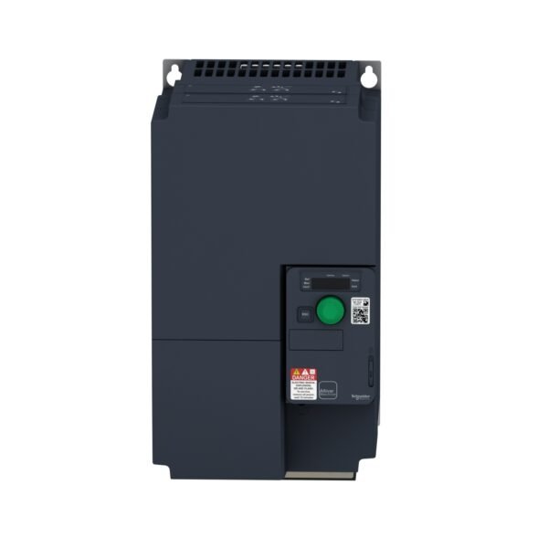
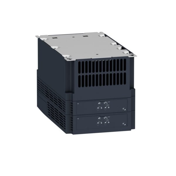
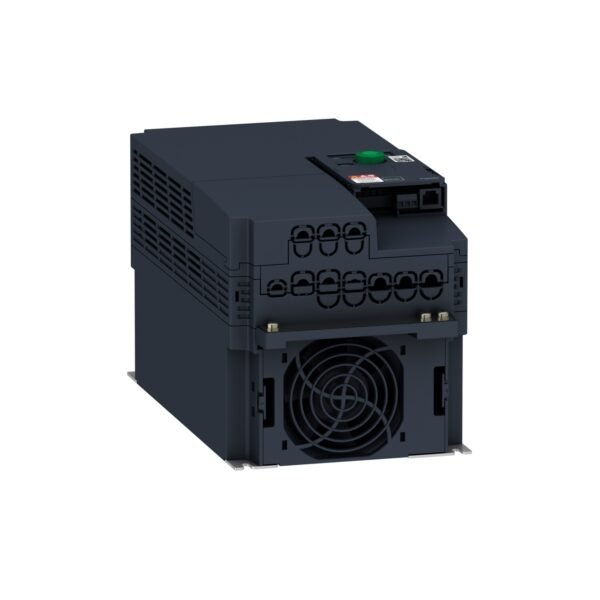
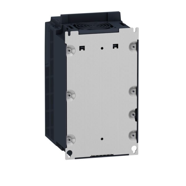
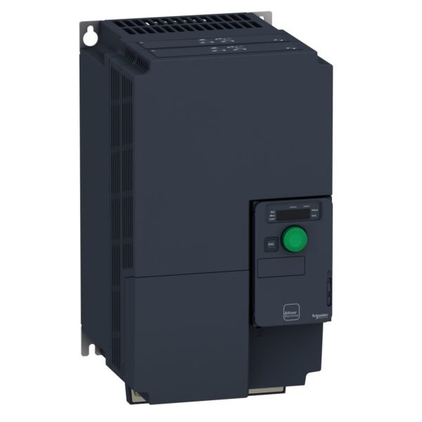

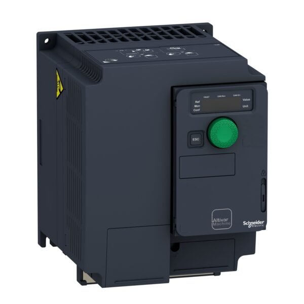
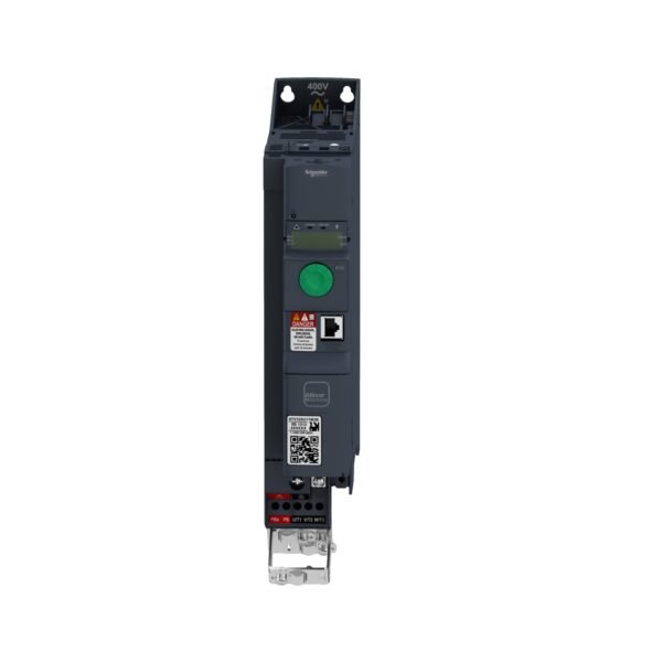
Schneider ATV320D15M3C | Variable speed drive, Altivar Machine ATV320, 15 kW, 200…240 V, 3 phases, compactSchneider
Schneider ATV320D15M3C | Variable speed drive, Altivar Machine ATV320, 15 kW, 200…240 V, 3 phases, compact
Original price was: EGP 1,075,362.00.EGP 59,145.00Current price is: EGP 59,145.00.
Description
Schneider ATV320D15M3C: The Ultimate Guide
Schneider Electric is a global leader in energy management and automation, known for its innovative products that cater to various industrial needs. One of their standout products is the Schneider ATV320D15M3C, a versatile and efficient variable frequency drive (VFD) designed to optimize motor control and enhance productivity.
What is the Schneider ATV320D15M3C?
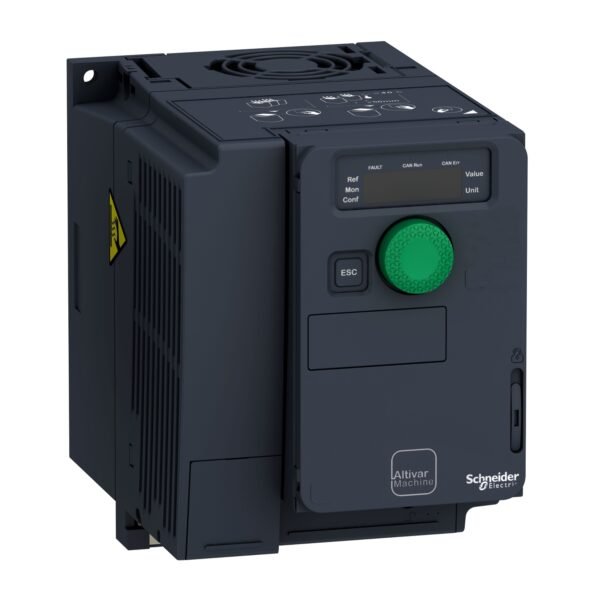
The Schneider ATV320D15M3C is a compact and robust variable frequency drive that is widely used in industrial applications. This model is part of Schneider Electric’s ATV320 series, which is known for its reliability and advanced features. It is designed to provide precise motor control, improve energy efficiency, and ensure high performance in various demanding environments.
Key Features of the Schneider ATV320D15M3C
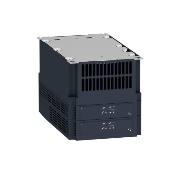
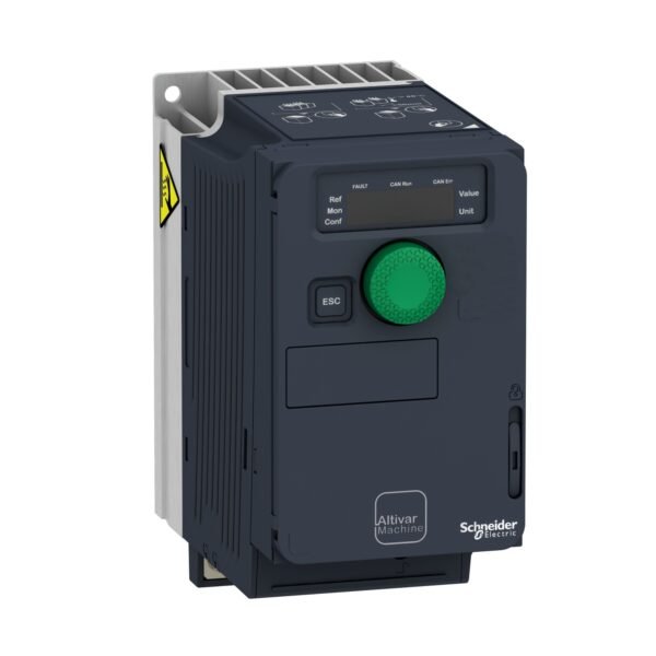
Compact Design
The ATV320D15M3C features a compact and space-saving design, making it easy to integrate into existing systems. Its small footprint allows for flexible installation even in confined spaces.
Energy Efficiency
One of the standout features of the ATV320D15M3C is its energy efficiency. By optimizing motor performance, this VFD helps reduce energy consumption, leading to significant cost savings over time.
High Performance
The ATV320D15M3C is designed to deliver high performance, ensuring smooth and precise motor control. It is capable of handling various load types and provides consistent performance even under challenging conditions.
Technical Specifications
Power Ratings
The Schneider ATV320D15M3C is rated for a power range of 1.5 kW (2 HP), making it suitable for a variety of industrial applications. It is designed to handle medium-sized motors with ease.
Voltage Requirements
This model operates on a three-phase power supply with a voltage range of 200-240V. It is compatible with most industrial power systems, ensuring seamless integration.
Environmental Ratings
The ATV320D15M3C is built to withstand harsh environmental conditions. It has an IP20 rating, indicating that it is protected against solid objects and provides adequate ventilation for cooling.
Applications of the Schneider ATV320D15M3C
Industries
The ATV320D15M3C is commonly used in various industries, including manufacturing, water treatment, HVAC, and more. Its versatility makes it suitable for a wide range of applications.
Machinery and Processes
This VFD is ideal for controlling pumps, fans, conveyors, and other types of machinery. It provides precise speed control, enhancing the efficiency and performance of industrial processes.
Installation and Setup
Step-by-Step Installation Guide
- Mounting: Secure the VFD in a well-ventilated area to ensure proper cooling.
- Wiring: Connect the power supply and motor cables according to the wiring diagram provided by Schneider Electric.
- Configuration: Use the built-in keypad or software tools to configure the VFD settings as per the application requirements.
- Testing: Perform a test run to ensure the VFD is functioning correctly and the motor is operating as expected.
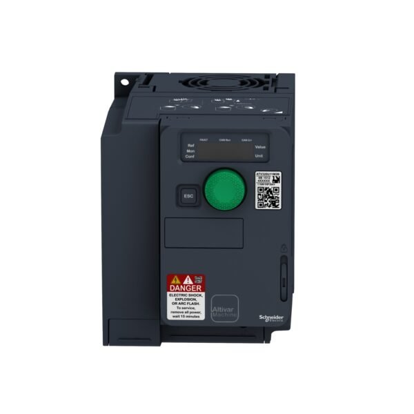
Safety Precautions
- Always disconnect power before performing any installation or maintenance work.
- Follow the manufacturer’s guidelines and local electrical codes to ensure safe and reliable operation.
Operating the Schneider ATV320D15M3C
Basic Operation Instructions
- Use the keypad to start and stop the motor.
- Adjust the speed using the up and down arrows.
- Monitor the display for real-time feedback on motor performance.
Advanced Features and Settings
- Programmable Inputs/Outputs: Customize the VFD’s behavior based on specific application needs.
- Communication Protocols: Integrate the VFD with other control systems using Modbus or other supported protocols.
- Protective Functions: Utilize built-in protection features such as overload protection, short circuit protection, and thermal management to safeguard the VFD and connected motor.
Maintenance Tips
Regular Maintenance Routines
- Visual Inspections: Regularly check for any signs of wear or damage.
- Cleaning: Keep the VFD clean and free from dust and debris.
- Firmware Updates: Ensure the VFD firmware is up to date to benefit from the latest features and improvements.
Troubleshooting Common Issues
- Overheating: Check for proper ventilation and remove any obstructions.
- Motor Stalling: Verify the motor and load are within the VFD’s capacity.
- Communication Errors: Ensure all connections are secure and properly configured.
Advantages of Using the Schneider ATV320D15M3C
Cost Savings
By optimizing energy consumption and reducing wear and tear on motors, the ATV320D15M3C helps lower operational costs.
Enhanced Productivity
The precise control and advanced features of this VFD contribute to improved productivity and efficiency in industrial operations.
Longevity and Durability
Built to withstand harsh environments, the ATV320D15M3C offers long-lasting performance and reliability.
Additional information
| brands | Schneider Electric |
|---|


Reviews
There are no reviews yet.