
No products in the cart.
-45%On Sale
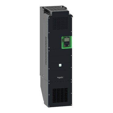
Schneider ATV630C13N4 | variable speed drive, Altivar Process ATV600, ATV630, 130kW, 380 to 480V, IP00
Schneider ATV630C13N4 | variable speed drive, Altivar Process ATV600, ATV630, 130kW, 380 to 480V, IP00
Original price was: EGP 963,129.00.EGP 529,721.00Current price is: EGP 529,721.00.
Description
Schneider ATV630C13N4: The Ultimate Guide to a Powerful Variable Speed Drive
In today’s fast-paced industrial world, having the right equipment can make all the difference. One such essential piece of equipment is the variable speed drive, and it stands out as a top choice. This article will delve into the details of it, exploring its features, benefits, applications, and more.
What is the Schneider ATV630C13N4?
it is a variable speed drive designed to optimize the performance of electric motors in various industrial applications. With advanced features and robust design, it ensures efficiency and reliability.
Key Specifications and Features
- Power Range: 0.75 kW to 800 kW
- Voltage: 380V to 480V
- Protection Rating: IP21, IP55
- Built-in Energy Monitoring: Tracks energy consumption and efficiency
- Connectivity: Supports Modbus, Ethernet, and other communication protocols
Advantages of Using Schneider ATV630C13N4
Energy Efficiency
One of the standout benefits of it is its energy efficiency. By optimizing motor performance, it significantly reduces energy consumption, leading to lower operational costs and a smaller environmental footprint.
Enhanced Motor Control
The drive offers precise control over motor speed and torque, enhancing the performance of various applications. This precision helps in achieving better process control, improved product quality, and increased operational efficiency.
Extended Equipment Life
By reducing mechanical stress on motors and other connected equipment, the Schneider ATV630C13N4 helps extend the life of your machinery. This not only lowers maintenance costs but also reduces downtime, ensuring continuous productivity.
Applications of Schneider ATV630C13N4
Industrial Automation
In the realm of industrial automation, the Schneider ATV630C13N4 plays a crucial role. It is used in conveyor systems, manufacturing lines, and other automated processes where precise motor control is essential.
HVAC Systems
The drive is also widely used in HVAC systems to control fans, pumps, and compressors. By adjusting the motor speed according to demand, it enhances the efficiency of heating, ventilation, and air conditioning systems.
Water and Wastewater Treatment
In water and wastewater treatment facilities, it helps in controlling pumps and blowers, ensuring optimal performance and energy savings.
Key Features of Schneider ATV630C13N4
Altivar Process Design
it is part of the Altivar Process range, known for its robustness and reliability. It is designed to handle harsh industrial environments while delivering top-notch performance.
Built-in Energy Monitoring
With built-in energy monitoring, you can keep track of energy consumption in real-time. This feature helps in identifying areas where energy savings can be made, contributing to overall efficiency.
Connectivity and Integration
The drive supports multiple communication protocols, making it easy to integrate into existing systems. Whether it’s Modbus, Ethernet, or another protocol, the Schneider ATV630C13N4 ensures seamless connectivity.
Installation and Setup
Step-by-Step Installation Guide
- Mounting the Drive: Ensure it is securely mounted in a suitable location.
- Electrical Connections: Follow the wiring diagram for correct connections.
- Initial Configuration: Set the basic parameters using the user interface.
- Testing: Run initial tests to ensure proper operation.
Configuration Tips
- Utilize the built-in wizards for easy setup.
- Regularly update the firmware to benefit from the latest features and improvements.
User Interface and Accessibility
Easy-to-Use Interface
The Schneider ATV630C13N4 comes with an intuitive user interface that simplifies configuration and monitoring. The clear display and easy navigation make it user-friendly even for those with minimal technical expertise.
Remote Monitoring and Control
With remote monitoring capabilities, you can control and monitor the drive from anywhere. This feature is particularly useful for large facilities where on-site access may be limited.
Troubleshooting and Maintenance
Common Issues and Solutions
- Overheating: Ensure proper ventilation and avoid overloading the drive.
- Communication Errors: Check cable connections and network settings.
- Unexpected Shutdowns: Investigate for electrical supply issues or parameter misconfigurations.
Routine Maintenance Practices
- Regularly inspect and clean the drive.
- Check for firmware updates and install them as needed.
- Perform periodic testing to ensure optimal performance.
Cost Considerations
Initial Investment vs. Long-Term Savings
While the initial cost of it may be higher than some alternatives, the long-term savings in energy costs and maintenance make it a worthwhile investment.
Return on Investment (ROI) Analysis
By reducing energy consumption and extending equipment life, it offers a strong return on investment. Many users report recouping their investment within a few years of installation.
Additional information
| brands | Schneider Electric |
|---|
Specifications
| Range of Product | Altivar Process ATV600 |
|---|---|
| Product or Component Type | Variable speed drive |
| Product Specific Application | Process and utilities |
| Device short name | ATV630 |
| variant | Standard version |
| product destination | Asynchronous motors Synchronous motors |
| EMC filter | Integrated 492.1 ft (150 m) IEC 61800-3 category C3 |
| IP degree of protection | IP00IEC 61800-5-1 IP00IEC 60529 IP21 with kit VW3A9704)IEC 61800-5-1 IP21 with kit VW3A9704)IEC 60529 |
| [Us] rated supply voltage | 380...480 V |
| Type of cooling | Forced convection |
| Supply frequency | 50...60 Hz - 5...5 % |
| [Us] rated supply voltage | 380...480 V - 15...10 % |
| Motor power kW | 132 kW normal duty) 110 kW heavy duty) |
| Maximum Horse Power Rating | 200 hp normal duty 150 hp heavy duty |
| Line current | 237 A 380 V normal duty) 213 A 480 V normal duty) 201 A 380 V heavy duty) 165 A 480 V heavy duty) |
| Prospective line Isc | 50 kA |
| Apparent power | 161.4 kVA 480 V normal duty) 121.8 kVA 480 V heavy duty) |
| Continuous output current | 250 A 2.5 kHz normal duty 211 A 2.5 kHz heavy duty |
| Asynchronous motor control profile | Constant torque standard Optimized torque mode Variable torque standard |
| Synchronous motor control profile | Permanent magnet motor Synchronous reluctance motor |
| Speed drive output frequency | 0.1…500 Hz |
| Nominal switching frequency | 2.5 kHz |
| Switching frequency | 2.5...8 kHz with derating factor 2...8 kHz adjustable |
| Safety function | STO (safe torque off) SIL 3 |
| Discrete input logic | 16 preset speeds |
| Communication Port Protocol | Ethernet Modbus TCP Modbus serial |
| Option card | Slot A communication module, Profibus DP V1 Slot A communication module, PROFINET Slot A communication module, DeviceNet Slot A communication module, Modbus TCP/EtherNet/IP Slot A communication module, CANopen daisy chain RJ45 Slot A communication module, CANopen SUB-D 9 Slot A communication module, CANopen screw terminals Slot A/slot B digital and analog I/O extension module Slot A/slot B output relay extension module Slot A communication module, Ethernet IP/Modbus TCP/MD-Link communication module, BACnet MS/TP communication module, Ethernet Powerlink |
| Mounting Mode | Wall mount |
|---|---|
| Maximum transient current | 275 A 60 s normal duty) 316.5 A 60 s heavy duty) |
| Phase | 3 phase |
| Discrete output number | 0 |
| Discrete output type | Relay outputs R1A, R1B, R1C 250 V AC 3000 mA Relay outputs R1A, R1B, R1C 30 V DC 3000 mA Relay outputs R2A, R2C 250 V AC 5000 mA Relay outputs R2A, R2C 30 V DC 5000 mA Relay outputs R3A, R3C 250 V AC 5000 mA Relay outputs R3A, R3C 30 V DC 5000 mA |
| Output voltage | <= power supply voltage |
| Permissible temporary current boost | 1.1 x In 60 s normal duty) 1.5 x In 60 s heavy duty) |
| Motor slip compensation | Adjustable Not available in permanent magnet motor law Automatic whatever the load Can be suppressed |
| Acceleration and deceleration ramps | Linear adjustable separately from 0.01...9999 s |
| Physical interface | Ethernet 2-wire RS 485 |
| Braking to standstill | By DC injection |
| Protection type | Thermal protection motor Safe torque off motor Motor phase break motor Thermal protection drive Safe torque off drive Overheating drive Overcurrent between output phases and earth drive Overload of output voltage drive Short-circuit protection drive Motor phase break drive Overvoltages on the DC bus drive Line supply overvoltage drive Line supply undervoltage drive Line supply phase loss drive Overspeed drive Break on the control circuit drive |
| Transmission Rate | 10, 100 Mbits 4800 bps, 9600 bps, 19200 bps, 38.4 Kbps |
| Frequency resolution | Display unit 0.1 Hz Analog input 0.012/50 Hz |
| Transmission frame | RTU |
| Electrical connection | Control removable screw terminals 0.5...1.5 mm² AWG 20...AWG 16 Line side screw terminal 2 x 70...3 x 120 mm² 2 x AWG 2/0...2 x 300 kcmil Motor screw terminal 2 x 70...3 x 120 mm² 2 x AWG 2/0...2 x 300 kcmil |
| Connector type | RJ45 on the remote graphic terminal)Ethernet/Modbus TCP RJ45 on the remote graphic terminal)Modbus serial |
| Data format | 8 bits, configurable odd, even or no parity |
| Type of polarization | No impedance |
| Exchange mode | Half duplex, full duplex, autonegotiation Ethernet/Modbus TCP |
| Number of addresses | 1…247 Modbus serial |
| Method of access | Slave Modbus TCP |
| Supply | External supply for digital inputs 24 V DC 19…30 V), <1.25 mA overload and short-circuit protection Internal supply for reference potentiometer (1 to 10 kOhm) 10.5 V DC +/- 5 %, <10 mA overload and short-circuit protection Internal supply for digital inputs and STO 24 V DC 21…27 V), <200 mA overload and short-circuit protection |
| Local signalling | For local diagnostic 3 LEDs for embedded communication status 3 LEDs (dual colour) for communication module status 4 LEDs (dual colour) for presence of voltage 1 LED (red) |
| Width | 12.6 in (320 mm) |
| Height | 33.5 in (852 mm) |
| Depth | 15.4 in (390 mm) |
| Net Weight | 180.8 lb(US) (82 kg) |
| Analogue input number | 3 |
| Analogue input type | AI1, AI2, AI3 software-configurable voltage 0...10 V DC 31.5 kOhm 12 bits AI1, AI2, AI3 software-configurable current 0...20 mA 250 Ohm 12 bits AI2 voltage analog input - 10...10 V DC 31.5 kOhm 12 bits |
| Discrete input number | 8 |
| Discrete input type | DI7, DI8 programmable as pulse input 0…30 kHz, 24 V DC <= 30 V) |
| Input compatibility | DI1...DI6 discrete input level 1 PLC IEC 61131-2 DI5, DI6 discrete input level 1 PLC IEC 65A-68 STOA, STOB discrete input level 1 PLC IEC 61131-2 |
| Discrete input logic | Positive logic (source) DI1...DI8), < 5 V, > 11 V Negative logic (sink) DI1...DI8), > 16 V, < 10 V |
| Analogue output number | 2 |
| Analogue output type | Software-configurable voltage AQ1, AQ2 0...10 V DC 470 Ohm 10 bits Software-configurable current AQ1, AQ2 0...20 mA 10 bits Software-configurable current DQ-, DQ+ 30 V DC Software-configurable current DQ-, DQ+ 100 mA |
| Sampling duration | 2 ms +/- 0.5 ms DI1...DI4) - discrete input 5 ms +/- 1 ms DI5, DI6) - discrete input 5 ms +/- 0.1 ms AI1, AI2, AI3) - analog input 10 ms +/- 1 ms AO1) - analog output |
| Accuracy | +/- 0.6 % AI1, AI2, AI3 for a temperature variation 60 °C analog input +/- 1 % AO1, AO2 for a temperature variation 60 °C analog output |
| Linearity error | AI1, AI2, AI3 +/- 0.15 % of maximum value analog input AO1, AO2 +/- 0.2 % analog output |
| Relay output number | 3 |
| Relay output type | Configurable relay logic R1 fault relay NO/NC 100000 cycles Configurable relay logic R2 sequence relay NO 100000 cycles Configurable relay logic R3 sequence relay NO 100000 cycles |
| Refresh time | Relay output R1, R2, R3)5 ms +/- 0.5 ms) |
| Minimum switching current | Relay output R1, R2, R3 5 mA 24 V DC |
| Maximum switching current | Relay output R1, R2, R3 resistive, cos phi = 1 3 A 250 V AC Relay output R1, R2, R3 resistive, cos phi = 1 3 A 30 V DC Relay output R1, R2, R3 inductive, cos phi = 0.4 7 ms 2 A 250 V AC Relay output R1, R2, R3 inductive, cos phi = 0.4 7 ms 2 A 30 V DC |
| Isolation | Between power and control terminals |
| Maximum output frequency | 500 kHz |
| Maximum Input Current per Phase | 237.0 A |
| Variable speed drive application selection | Building - HVAC compressor centrifugal Food and beverage processing other application Mining mineral and metal fan Mining mineral and metal pump Oil and gas fan Water and waste water other application Building - HVAC screw compressor Food and beverage processing pump Food and beverage processing fan Food and beverage processing atomization Oil and gas electro submersible pump (ESP) Oil and gas water injection pump Oil and gas jet fuel pump Oil and gas compressor for refinery Water and waste water centrifuge pump Water and waste water positive displacement pump Water and waste water electro submersible pump (ESP) Water and waste water screw pump Water and waste water lobe compressor Water and waste water screw compressor Water and waste water compressor centrifugal Water and waste water fan Water and waste water conveyor Water and waste water mixer |
| Motor power range AC-3 | 110…220 kW 380…440 V 3 phase 110…220 kW 480…500 V 3 phase |
| Quantity per Set | 1 |
| enclosure mounting | Wall mounted |
| Insulation resistance | > 1 MOhm 500 V DC for 1 minute to earth |
|---|---|
| Noise level | 69.9 dB 86/188/EEC |
| Power dissipation in W | Forced convection 2755 W 380 V 2.5 kHz |
| Volume of cooling air | 158506.07 Gal/hr(US) (600 m3/h) |
| Operating position | Vertical +/- 10 degree |
| Maximum THDI | <48 % full load IEC 61000-3-12 |
| Electromagnetic compatibility | Electrostatic discharge immunity test level 3 IEC 61000-4-2 Radiated radio-frequency electromagnetic field immunity test level 3 IEC 61000-4-3 Electrical fast transient/burst immunity test level 4 IEC 61000-4-4 1.2/50 µs - 8/20 µs surge immunity test level 3 IEC 61000-4-5 Conducted radio-frequency immunity test level 3 IEC 61000-4-6 |
| Pollution degree | 2 IEC 61800-5-1 |
| Vibration resistance | 1.5 mm peak to peak 2…13 Hz)IEC 60068-2-6 1 gn 13…200 Hz)IEC 60068-2-6 |
| Shock resistance | 15 gn 11 ms IEC 60068-2-27 |
| Relative humidity | 5…95 % without condensation IEC 60068-2-3 |
| Ambient air temperature for operation | 5.0000000000…122.0000000000 °F (-15…50 °C) without derating) 122.0000000000…140.0000000000 °F (50…60 °C) with derating factor) |
| Ambient Air Temperature for Storage | -40.0000000000…158.0000000000 °F (-40…70 °C) |
| Operating altitude | <= 3280.84 ft (1000 m) without derating 1000...4800 m with current derating 1 % per 100 m |
| Product Certifications | DNV-GL ATEX zone 2/22 UL CSA TÜV ATEX INERIS |
| Marking | CE |
| Standards | UL 508C IEC 61800-3 IEC 61800-3 environment 1 category C2 EN/IEC 61800-3 environment 2 category C3 IEC 61800-5-1 IEC 61000-3-12 IEC 60721-3 IEC 61508 IEC 13849-1 |
| Overvoltage category | III |
| Regulation loop | Adjustable PID regulator |
| Noise level | 69.9 dB |
| Pollution degree | 2 |
| Category | US1CP4E22207 |
|---|---|
| Discount Schedule | CP4E |
| GTIN | 3606480796043 |
| Returnability | Yes |
| Country of origin | US |
| Unit Type of Package 1 | PCE |
|---|---|
| Number of Units in Package 1 | 1 |
| Package 1 Height | 26.0 in (66 cm) |
| Package 1 Width | 18.9 in (48 cm) |
| Package 1 Length | 40.6 in (103 cm) |
| Package 1 Weight | 201.7 lb(US) (91.5 kg) |


Reviews
There are no reviews yet.