Description

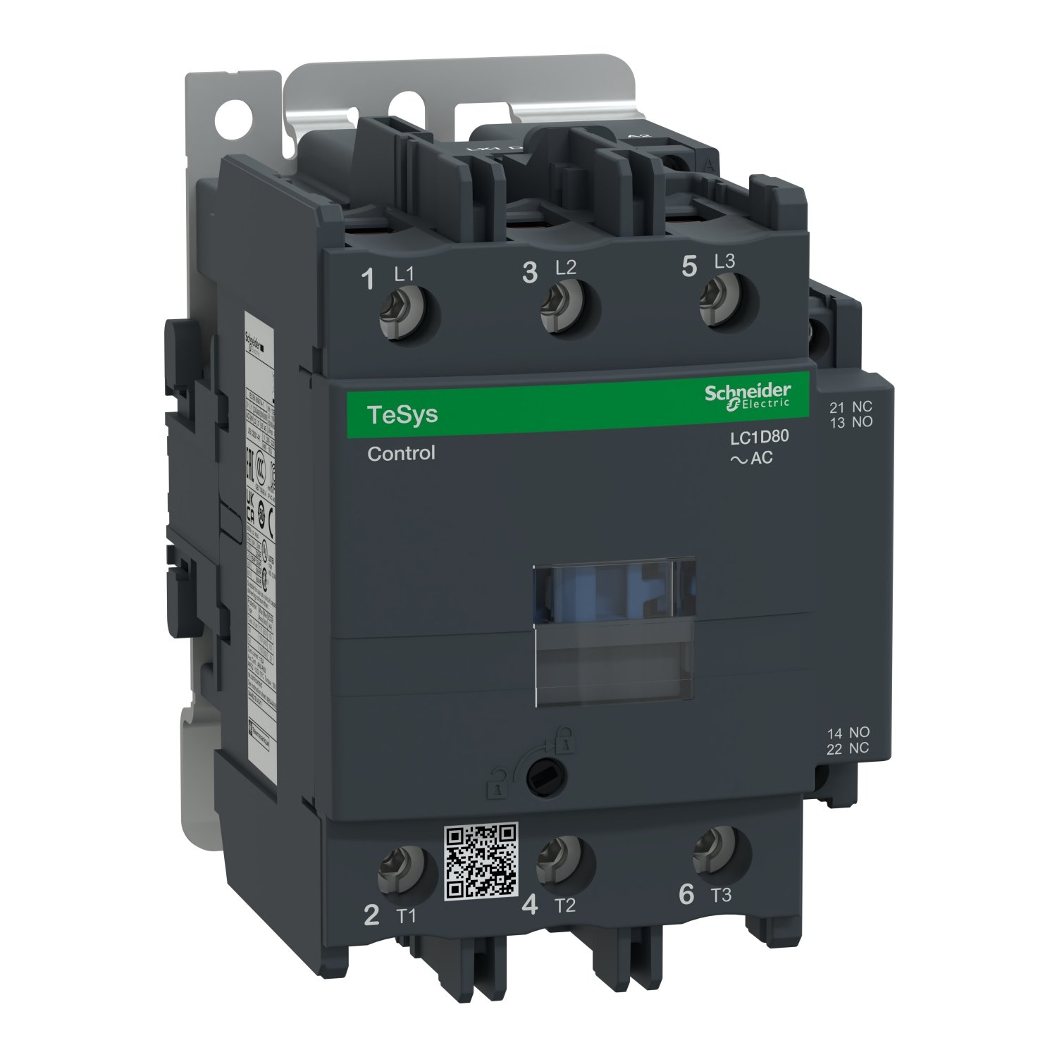
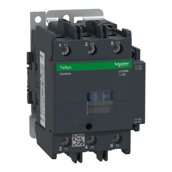
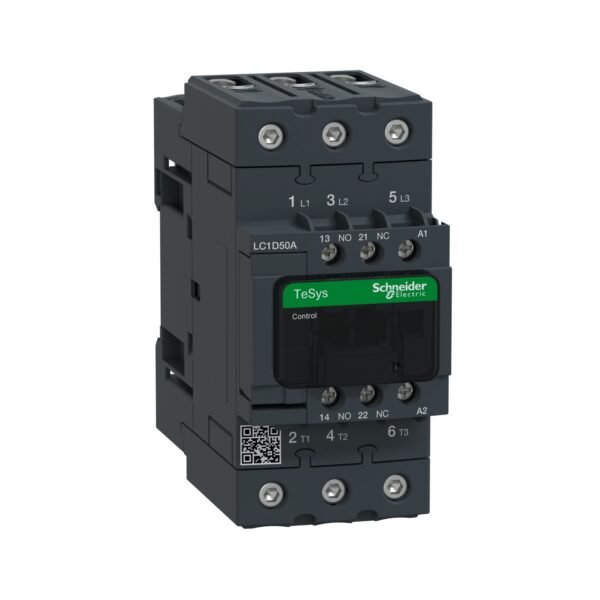
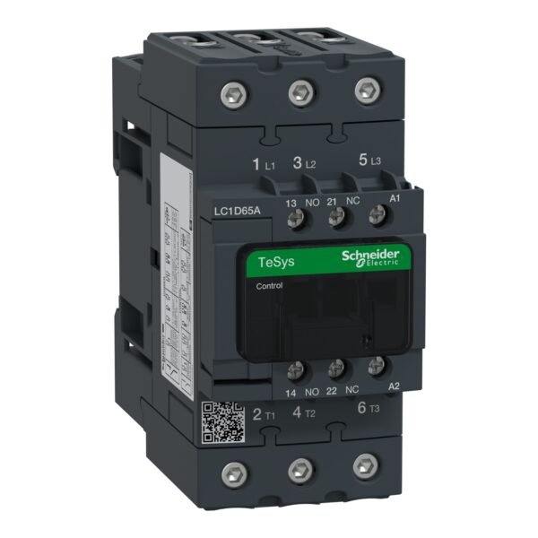
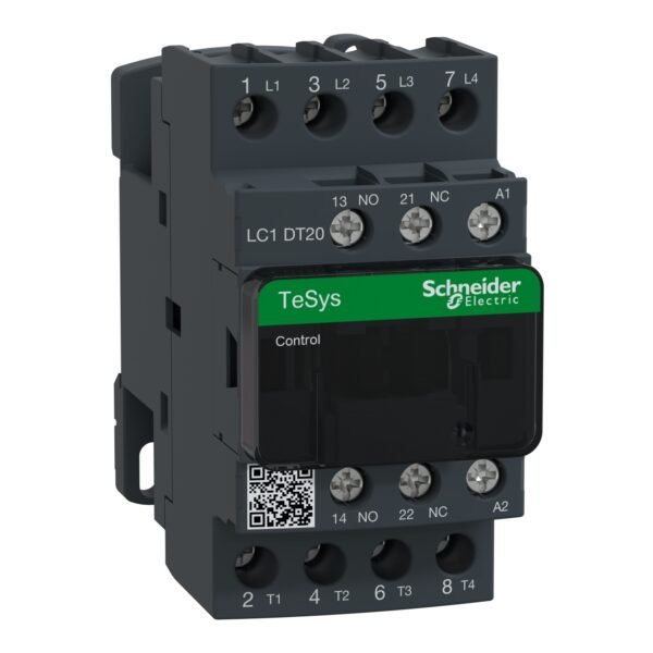
Schneider LC1D80F7| TeSys D contactor – 3P(3 NO) – AC-3 – <= 440 V 80 A – 110 V AC 50/60 Hz coil

Schneider LC1D80F7 Contactor: Detailed Overview

The Schneider LC1D80F7 is a robust and reliable contactor, designed for controlling motors and managing high-power loads in industrial applications. Renowned for its durability and performance, this contactor is an essential component in electrical control panels.

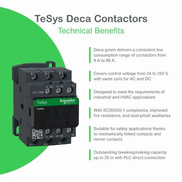
Technical Specifications

  • Model Number: LC1D80F7
  • Rated Current (AC-3): 80 A
  • Voltage Rating:
    • Coil Voltage: 110V AC
    • Operating Voltage: Up to 690V AC
  • Power Rating: Supports motors up to 37 kW at 400V
  • Auxiliary Contacts: 1 NO (Normally Open) + 1 NC (Normally Closed)
  • Frequency Range: 25 to 400 Hz
  • Mounting Type: Compatible with DIN rail or panel mounting
  • Dimensions: Compact, space-efficient design for streamlined integration.

Key Features

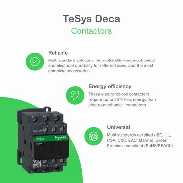
  1. Reliable Performance:
    Built to handle high operational demands with consistent and efficient performance.
  2. Compact and Flexible Design:
    Ideal for installations with limited space, offering flexibility in control panel designs.
  3. Enhanced Safety Standards:
    Equipped with superior insulation and adherence to global safety certifications for secure operations.
  4. Energy-Efficient Coil:
    The low-consumption coil minimizes energy usage while maintaining high performance.
  5. Modular Compatibility:
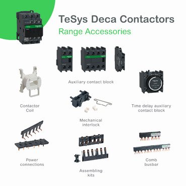
    Integrates seamlessly with Schneider Electric’s auxiliary modules, timers, and interlocking systems for tailored solutions.

Applications

The LC1D80F7 is suitable for a wide array of applications, including:

  • Motor Control: Efficiently controls motor starting, stopping, and reversing functions.
  • Industrial Automation: Plays a key role in automated systems requiring precise and reliable load management.
  • Power Distribution Systems: Ensures smooth and safe operation in factories and commercial facilities.
  • HVAC Systems: Supports efficient control of heating, ventilation, and air conditioning units.

Installation and Maintenance

  • Installation Guidelines:
    • Ensure proper alignment on DIN rails or panels for secure mounting.
    • Match the coil voltage to the system’s requirements before installation.
  • Maintenance Tips:
    • Regularly inspect for wear and debris to maintain optimal functionality.
    • Test auxiliary contacts periodically to ensure consistent operation.

Additional information

brands

Schneider Electric

Specifications

Main
Range TeSys
Range of product TeSys Deca
Product or component type Contactor
Device short name LC1D
Contactor application Motor control Resistive load
Utilisation category AC-3 AC-3e AC-4 AC-1
Poles description 3P
[Ue] rated operational voltage Power circuit: <= 300 V DC 25...400 Hz Power circuit: <= 690 V AC
[Ie] rated operational current 125 A (at <60 °C) at <= 1000 V AC AC-1 for power circuit 80 A (at <60 °C) at <= 440 V AC AC-3 for power circuit 80 A (at <60 °C) at <= 440 V AC-3e for power circuit
[Uc] control circuit voltage 110 V AC 50/60 Hz
Complementary
Motor power kW 22 kW at 220...230 V AC 50/60 Hz (AC-3) 37 kW at 380...400 V AC 50/60 Hz (AC-3) 45 kW at 415...440 V AC 50/60 Hz (AC-3) 55 kW at 500 V AC 50/60 Hz (AC-3) 45 kW at 660...690 V AC 50/60 Hz (AC-3) 15 kW at 400 V AC 50/60 Hz (AC-4) 22 kW at 220...230 V AC 50/60 Hz (AC-3e) 37 kW at 380...400 V AC 50/60 Hz (AC-3e) 45 kW at 415...440 V AC 50/60 Hz (AC-3e) 55 kW at 500 V AC 50/60 Hz (AC-3e) 45 kW at 660...690 V AC 50/60 Hz (AC-3e)
Motor power hp 7.5 hp at 120 V AC 50/60 Hz for 1 phase motors 15 hp at 230/240 V AC 50/60 Hz for 1 phase motors 30 hp at 200/208 V AC 50/60 Hz for 3 phases motors 30 hp at 230/240 V AC 50/60 Hz for 3 phases motors 60 hp at 460/480 V AC 50/60 Hz for 3 phases motors 60 hp at 575/600 V AC 50/60 Hz for 3 phases motors
Compatibility code LC1D
Pole contact composition 3 NO
Protective cover With
[Ith] conventional free air thermal current 10 A (at 60 °C) for signalling circuit 125 A (at 60 °C) for power circuit
Irms rated making capacity 140 A AC for signalling circuit conforming to IEC 60947-5-1 250 A DC for signalling circuit conforming to IEC 60947-5-1 1100 A at 440 V for power circuit conforming to IEC 60947
Rated breaking capacity 1100 A at 440 V for power circuit conforming to IEC 60947
[Icw] rated short-time withstand current 640 A 40 °C - 10 s for power circuit 990 A 40 °C - 1 s for power circuit 135 A 40 °C - 10 min for power circuit 320 A 40 °C - 1 min for power circuit 100 A - 1 s for signalling circuit 120 A - 500 ms for signalling circuit 140 A - 100 ms for signalling circuit
Associated fuse rating 10 A gG for signalling circuit conforming to IEC 60947-5-1 200 A gG at <= 690 V coordination type 1 for power circuit 160 A gG at <= 690 V coordination type 2 for power circuit
Average impedance 0.8 mOhm - Ith 125 A 50 Hz for power circuit
Power dissipation per pole 5.1 W AC-3 12.5 W AC-1 5.1 W AC-3e
[Ui] rated insulation voltage Power circuit: 600 V CSA certified Power circuit: 600 V UL certified Power circuit: 1000 V conforming to IEC 60947-4-1 Signalling circuit: 690 V conforming to IEC 60947-1 Signalling circuit: 600 V CSA certified Signalling circuit: 600 V UL certified
Overvoltage category III
Pollution degree 3
[Uimp] rated impulse withstand voltage 8 kV conforming to IEC 60947
Safety reliability level B10d = 1369863 cycles contactor with nominal load conforming to EN/ISO 13849-1 B10d = 20000000 cycles contactor with mechanical load conforming to EN/ISO 13849-1
Mechanical durability 4 Mcycles
Electrical durability 0.8 Mcycles 125 A AC-1 at Ue <= 440 V 1.5 Mcycles 80 A AC-3 at Ue <= 440 V 1.5 Mcycles 80 A AC-3e at Ue <= 440 V
Control circuit type AC at 50/60 Hz standard
Coil technology Without built-in suppressor module
Control circuit voltage limits 0.85...1.1 Uc (-40…55 °C):operational AC 60 Hz 0.3...0.6 Uc (-40…70 °C):drop-out AC 50/60 Hz 0.8...1.1 Uc (-40…55 °C):operational AC 50 Hz 1...1.1 Uc (55…70 °C):operational AC 50/60 Hz
Inrush power in VA 245 VA 60 Hz cos phi 0.75 (at 20 °C) 245 VA 50 Hz cos phi 0.75 (at 20 °C)
Hold-in power consumption in VA 26 VA 60 Hz cos phi 0.3 (at 20 °C) 26 VA 50 Hz cos phi 0.3 (at 20 °C)
Heat dissipation 6…10 W at 50/60 Hz
Operating time 20...35 ms closing 6...20 ms opening
Maximum operating rate 3600 cyc/h 60 °C
Maximum operating rate 3600 cyc/h at 60 °C
Connections - terminals Control circuit: screw clamp terminals 2 1…2.5 mm² - cable stiffness: flexible with cable end Control circuit: screw clamp terminals 1 1…2.5 mm² - cable stiffness: flexible with cable end Control circuit: screw clamp terminals 1 1…4 mm² - cable stiffness: flexible without cable end Control circuit: screw clamp terminals 2 1…4 mm² - cable stiffness: flexible without cable end Control circuit: screw clamp terminals 1 1…4 mm² - cable stiffness: solid without cable end Control circuit: screw clamp terminals 2 1…4 mm² - cable stiffness: solid without cable end Power circuit: connector 1 4…50 mm² - cable stiffness: flexible without cable end Power circuit: connector 2 4…25 mm² - cable stiffness: flexible without cable end Power circuit: connector 1 4…50 mm² - cable stiffness: flexible with cable end Power circuit: connector 2 4…16 mm² - cable stiffness: flexible with cable end Power circuit: connector 1 4…50 mm² - cable stiffness: solid without cable end Power circuit: connector 2 4…25 mm² - cable stiffness: solid without cable end
Tightening torque Control circuit: 1.2 N.m - on screw clamp terminals - with screwdriver flat Ø 6 mm Control circuit: 1.2 N.m - on screw clamp terminals - with screwdriver Philips No 2 Power circuit: 12 N.m - on connector - with screwdriver flat Ø 6 to Ø 8 mm Power circuit: 12 N.m - on connector hexagonal screw head 4 mm Control circuit: 1.2 N.m - on screw clamp terminals - with screwdriver pozidriv No 2
Auxiliary contact composition 1 NO + 1 NC
Auxiliary contacts type type mechanically linked 1 NO + 1 NC conforming to IEC 60947-5-1 type mirror contact 1 NC conforming to IEC 60947-4-1
Signalling circuit frequency 25...400 Hz
Minimum switching voltage 17 V for signalling circuit
Minimum switching current 5 mA for signalling circuit
Insulation resistance > 10 MOhm for signalling circuit
Non-overlap time 1.5 ms on de-energisation between NC and NO contact 1.5 ms on energisation between NC and NO contact
Mounting support Rail Plate
Environment
Standards EN 60947-4-1 EN 60947-5-1 IEC 60947-4-1 IEC 60947-5-1 CSA C22.2 No 14 UL 60947-4-1 IEC 60335-2-40:Annex JJ UL 60335-2-40:Annex JJ IEC 60335-1:Clause 30.2
Product certifications CCC UL CB Scheme CSA CE UKCA Marine EAC
IP degree of protection IP20 front face conforming to IEC 60529
Protective treatment TH conforming to IEC 60068-2-30
Climatic withstand conforming to IACS E10 exposure to damp heat
Permissible ambient air temperature around the device -40…60 °C 60…70 °C with derating
Operating altitude 0...3000 m
Fire resistance 850 °C conforming to IEC 60695-2-1
Flame retardance V1 conforming to UL 94
Mechanical robustness Vibrations contactor open (2 Gn, 5...300 Hz) Shocks contactor open (8 Gn for 11 ms) Vibrations contactor closed (3 Gn, 5...300 Hz) Shocks contactor closed (10 Gn for 11 ms)
Height 127 mm
Width 85 mm
Depth 130 mm
Net weight 1.59 kg
Packing Units
Unit Type of Package 1 PCE
Number of Units in Package 1 1
Package 1 Height 9.500 cm
Package 1 Width 13.400 cm
Package 1 Length 14.200 cm
Package 1 Weight 1.558 kg
Unit Type of Package 2 S02
Number of Units in Package 2 5
Package 2 Height 15.000 cm
Package 2 Width 30.000 cm
Package 2 Length 40.000 cm
Package 2 Weight 8.048 kg
Unit Type of Package 3 P06
Number of Units in Package 3 80
Package 3 Height 75.000 cm
Package 3 Width 60.000 cm
Package 3 Length 80.000 cm
Package 3 Weight 124.640 kg
Contractual warranty
Warranty 18 months

Main Document

Main Document

Data Sheet : LC1D80F7

Main Document

Data Sheet : LC1D80F7

Reviews (0)

Be the first to review “Schneider LC1D80F7 | TeSys D contactor – 3P(3 NO) – AC-3 – <= 440 V 80 A – 110 V AC 50/60 Hz coil”

Your email address will not be published. Required fields are marked *

Reviews

There are no reviews yet.

Product was successfully added to your cart!

Select at least 2 products
to compare