
No products in the cart.
-45%On Sale
Controllers (PLC & PAC) for Industrial machines, Industrial Automation and Control, Logic Controller - Modicon M221, Uncategorized
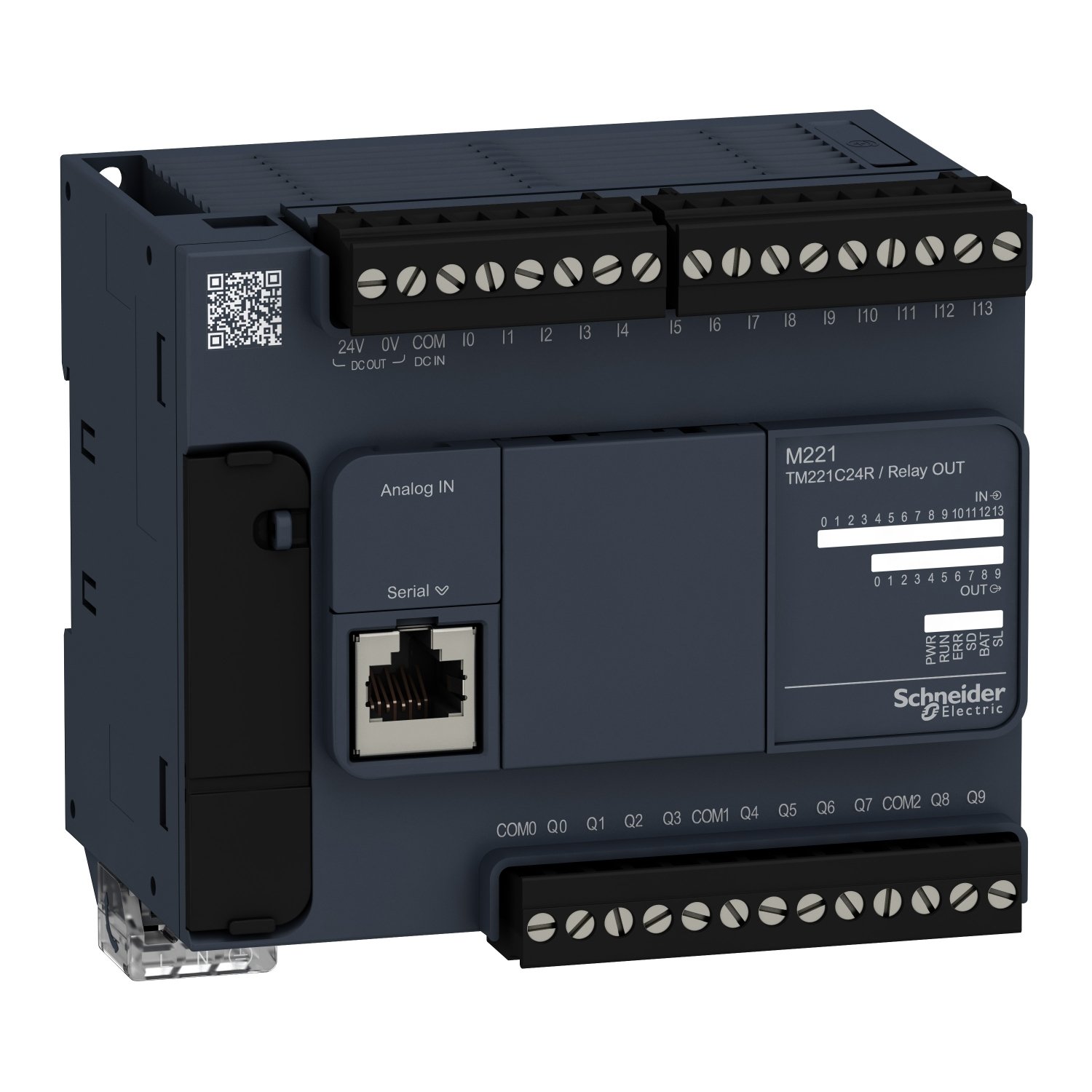
Schneider TM221C24R | controller M221 24 IO relay, Logic Controller
Schneider TM221C24R | controller M221 24 IO relay, Logic Controller
Original price was: EGP 466,146.00.EGP 256,381.00Current price is: EGP 256,381.00.
Description
Schneider TM221C24R | controller M221 24 IO relay, Logic Controller
Specifications:
-
Model: TM221C24R
-
Type: Logic Controller
-
Series: Modicon M221
-
I/O Configuration: 24 I/O (16 digital inputs, 8 digital outputs, relay type)
-
Power Supply: 24V DC
-
Programming Language: IEC 61131-3 (Structured Text, Ladder Diagram, Function Block Diagram, Instruction List)
-
Communication Ports: 1x Ethernet (Modbus TCP), 1x USB, 1x CANopen (optional)
-
Mounting Type: DIN rail mountable
-
Relay Outputs: 8 relay outputs (NO, 250VAC, 8A)
-
Digital Inputs: 16 digital inputs (12V DC)
-
Rated Input Voltage: 24V DC
Features:
-
Compact and Flexible:
-
The Modicon M221 controller is a compact and modular logic controller with 24 I/O channels, designed to provide flexible and cost-effective control solutions for a wide variety of industrial and automation applications.
-
-
24 I/O with Relay Outputs:
-
The TM221C24R comes with 16 digital inputs and 8 relay outputs. The relay outputs are rated for 250VAC, 8A, making it suitable for controlling relays, motors, and other electrical devices. The digital inputs accept 24V DC signals from various sensors and switches.
-
-
Powerful and Efficient Logic Control:
-
The Modicon M221 controller is designed to handle complex logic and control tasks while maintaining a compact form factor. It is ideal for small to medium-sized automation systems, providing efficient control and monitoring.
-
-
Built-in Communication Ports:
-
The TM221C24R controller features built-in communication ports, including Modbus TCP over Ethernet, USB, and an optional CANopen port. This allows seamless integration into industrial networks and offers versatile connectivity for remote monitoring, data exchange, and programming.
-
-
IEC 61131-3 Programming Standard:
-
The controller supports programming languages in line with the IEC 61131-3 standard, including Ladder Diagram (LD), Structured Text (ST), Function Block Diagram (FBD), and Instruction List (IL). This flexibility allows users to program the controller using their preferred language and the requirements of the application.
-
-
Easy Integration:
-
The TM221C24R is designed to easily integrate into existing automation systems, making it ideal for upgrading or expanding control systems. Its DIN rail mounting makes installation simple in control panels or enclosures.
-
-
Expandability:
-
Although this model features 24 I/O, the Modicon M221 series is modular, allowing for easy expansion by adding additional I/O modules if more I/O capacity is required in the future.
-
-
Cost-Effective Solution:
-
The Modicon M221 logic controller provides an affordable solution for automation applications without compromising on performance. It’s well-suited for small and medium-sized control systems, offering both functionality and value for money.
-
Applications:
-
Industrial Automation: Ideal for small-scale automation projects such as conveyors, packaging machines, or small production lines.
-
Building Automation: Can be used for controlling lighting, HVAC, security systems, and other systems in buildings.
-
Machine Control: Suitable for controlling machines in manufacturing processes, such as motors, actuators, and safety devices.
-
Energy Management: Used in monitoring and controlling energy consumption in industrial and commercial applications.
-
Process Control: Can be used to manage temperature, pressure, flow, and other variables in process control systems.
Additional information
| brands | Schneider Electric |
|---|
Specifications
| Range of product | Modicon M221 |
|---|---|
| Product or component type | Logic controller |
| [Us] rated supply voltage | 100...240 V AC |
| Discrete input number | 14, discrete input conforming to IEC 61131-2 Type 1 |
| Analogue input number | 2 at 0...10 V |
| Discrete output type | Relay normally open |
| Discrete output number | 10 relay |
| Discrete output voltage | 5...125 V DC 5...250 V AC |
| Discrete output current | 2 A |
| Discrete I/O number | 24 |
|---|---|
| Maximum number of I/O expansion module | 7 (local I/O-Architecture) 14 (remote I/O-Architecture) |
| Supply voltage limits | 85…264 V |
| network frequency | 50/60 Hz |
| Inrush current | 40 A |
| Maximum power consumption in VA | 55 VA at 100...240 V with max number of I/O expansion module 32 VA at 100...240 V without I/O expansion module |
| Power supply output current | 0.52 A 5 V for expansion bus 0.16 A 24 V for expansion bus |
| Discrete input logic | Sink or source (positive/negative) |
| Discrete input voltage | 24 V |
| Discrete input voltage type | DC |
| Analogue input resolution | 10 bits |
| LSB value | 10 mV |
| Conversion time | 1 ms per channel + 1 controller cycle time for analogue input analog input |
| Permitted overload on inputs | +/- 30 V DC for 5 min (maximum) for analog input +/- 13 V DC (permanent) for analog input |
| Voltage state 1 guaranteed | >= 15 V for input |
| Voltage state 0 guaranteed | <= 5 V for input |
| Discrete input current | 7 mA for discrete input 5 mA for fast input |
| Input impedance | 3.4 kOhm for discrete input 100 kOhm for analog input 4.9 kOhm for fast input |
| Response time | 35 µs turn-off, I2...I5 terminal(s) for input 10 ms turn-on for output 10 ms turn-off for output 5 µs turn-on, I0, I1, I6, I7 terminal(s) for fast input 35 µs turn-on, other terminals terminal(s) for input 5 µs turn-off, I0, I1, I6, I7 terminal(s) for fast input 100 µs turn-off, other terminals terminal(s) for input |
| Configurable filtering time | 0 ms for input 3 ms for input 12 ms for input |
| Output voltage limits | 125 V DC 277 V AC |
| Maximum current per output common | 4 A at COM 2 7 A at COM 0 7 A at COM 1 |
| Absolute accuracy error | +/- 1 % of full scale for analog input |
| Electrical durability | 100000 cycles AC-12, 120 V, 240 VA, resistive 100000 cycles AC-12, 240 V, 480 VA, resistive 300000 cycles AC-12, 120 V, 80 VA, resistive 300000 cycles AC-12, 240 V, 160 VA, resistive 100000 cycles AC-15, cos phi = 0.35, 120 V, 60 VA, inductive 100000 cycles AC-15, cos phi = 0.35, 240 V, 120 VA, inductive 300000 cycles AC-15, cos phi = 0.35, 120 V, 18 VA, inductive 300000 cycles AC-15, cos phi = 0.35, 240 V, 36 VA, inductive 100000 cycles AC-14, cos phi = 0.7, 120 V, 120 VA, inductive 100000 cycles AC-14, cos phi = 0.7, 240 V, 240 VA, inductive 300000 cycles AC-14, cos phi = 0.7, 120 V, 36 VA, inductive 300000 cycles AC-14, cos phi = 0.7, 240 V, 72 VA, inductive 100000 cycles DC-12, 24 V, 48 W, resistive 300000 cycles DC-12, 24 V, 16 W, resistive 100000 cycles DC-13, 24 V, 24 W, inductive (L/R = 7 ms) 300000 cycles DC-13, 24 V, 7.2 W, inductive (L/R = 7 ms) |
| Switching frequency | 20 switching operations/minute with maximum load |
| Mechanical durability | 20000000 cycles for relay output |
| Minimum load | 1 mA at 5 V DC for relay output |
| Protection type | Without protection at 5 A |
| Reset time | 1 s |
| Memory capacity | 256 kB for user application and data RAM with 10000 instructions 256 kB for internal variables RAM |
| Data backed up | 256 kB built-in flash memory for backup of application and data |
| Data storage equipment | 2 GB SD card (optional) |
| Battery type | BR2032 or CR2032X lithium non-rechargeable |
| Backup time | 1 year at 25 °C (by interruption of power supply) |
| Execution time for 1 KInstruction | 0.3 ms for event and periodic task |
| Execution time per instruction | 0.2 µs Boolean |
| Exct time for event task | 60 µs response time |
| Maximum size of object areas | 255 %C counters 8000 %MW memory words 512 %M memory bits 512 %KW constant words 255 %TM timers |
| Realtime clock | With |
| Clock drift | <= 30 s/month at 25 °C |
| Regulation loop | Adjustable PID regulator up to 14 simultaneous loops |
| Counting input number | 4 fast input (HSC mode) at 100 kHz 32 bits |
| counter function | A/B Single phase Pulse/direction |
| Integrated connection type | USB port with mini B USB 2.0 connector Non isolated serial link serial 1 with RJ45 connector and RS485 interface Non isolated serial link serial 2 with RJ45 connector and RS232/RS485 interface |
| Supply | (serial)serial link supply: 5 V, <200 mA |
| Transmission rate | 1.2...115.2 kbit/s (115.2 kbit/s by default) for bus length of 15 m for RS485 1.2...115.2 kbit/s (115.2 kbit/s by default) for bus length of 3 m for RS232 480 Mbit/s for USB |
| Communication port protocol | USB port: USB - SoMachine-Network Non isolated serial link: Modbus master/slave - RTU/ASCII or SoMachine-Network |
| Local signalling | 1 LED (green) for PWR 1 LED (green) for RUN 1 LED (red) for module error (ERR) 1 LED (green) for SD card access (SD) 1 LED (red) for BAT 1 LED (green) for SL1 1 LED (green) for SL2 1 LED per channel (green) for I/O state |
| Electrical connection | removable screw terminal block for inputs removable screw terminal block for outputs terminal block, 3 terminal(s) for connecting the 24 V DC power supply connector, 4 terminal(s) for analogue inputs Mini B USB 2.0 connector for a programming terminal |
| Maximum cable distance between devices | Shielded cable: <10 m for fast input Unshielded cable: <30 m for output Unshielded cable: <30 m for digital input Unshielded cable: <1 m for analog input |
| Insulation | Between input and internal logic at 500 V AC Non-insulated between analogue input and internal logic Non-insulated between analogue inputs Between supply and ground at 1500 V AC Between sensor power supply and ground at 500 V AC Between input and ground at 500 V AC Between output and ground at 1500 V AC Between supply and internal logic at 2300 V AC Between sensor power supply and internal logic at 500 V AC Between output and internal logic at 2300 V AC Between Ethernet terminal and internal logic at 500 V AC Between supply and sensor power supply at 2300 V AC |
| marking | CE |
| Sensor power supply | 24 V DC at 250 mA supplied by the controller |
| Mounting support | Top hat type TH35-15 rail conforming to IEC 60715 Top hat type TH35-7.5 rail conforming to IEC 60715 plate or panel with fixing kit |
| Height | 90 mm |
| Depth | 70 mm |
| Width | 110 mm |
| Net weight | 0.395 kg |
| Standards | IEC 61131-2 UL 508 CAN/CSA C22.2 No. 213 IACS E10 ANSI/ISA 12-12-01 |
|---|---|
| Product certifications | LR ABS DNV-GL RCM cULus EAC CE UKCA cULus HazLoc |
| Environmental characteristic | Ordinary and hazardous location |
| Resistance to electrostatic discharge | 8 kV in air conforming to IEC 61000-4-2 4 kV on contact conforming to IEC 61000-4-2 |
| Resistance to electromagnetic fields | 10 V/m 80 MHz...1 GHz conforming to IEC 61000-4-3 3 V/m 1.4 GHz...2 GHz conforming to IEC 61000-4-3 1 V/m 2...2.7 GHz conforming to IEC 61000-4-3 |
| Resistance to magnetic fields | 30 A/m 50/60 Hz conforming to IEC 61000-4-8 |
| Resistance to fast transients | 2 kV (power lines) conforming to IEC 61000-4-4 2 kV (relay output) conforming to IEC 61000-4-4 1 kV (I/O) conforming to IEC 61000-4-4 1 kV (Ethernet line) conforming to IEC 61000-4-4 1 kV (serial link) conforming to IEC 61000-4-4 |
| Surge withstand | 2 kV power lines (AC) common mode conforming to IEC 61000-4-5 2 kV relay output common mode conforming to IEC 61000-4-5 1 kV I/O common mode conforming to IEC 61000-4-5 1 kV shielded cable common mode conforming to IEC 61000-4-5 0.5 kV power lines (DC) differential mode conforming to IEC 61000-4-5 1 kV power lines (AC) differential mode conforming to IEC 61000-4-5 1 kV relay output differential mode conforming to IEC 61000-4-5 0.5 kV power lines (DC) common mode conforming to IEC 61000-4-5 |
| Resistance to conducted disturbances | 10 V 0.15...80 MHz conforming to IEC 61000-4-6 3 V 0.1...80 MHz conforming to Marine specification (LR, ABS, DNV, GL) 10 V spot frequency (2, 3, 4, 6.2, 8.2, 12.6, 16.5, 18.8, 22, 25 MHz) conforming to Marine specification (LR, ABS, DNV, GL) |
| Electromagnetic emission | Conducted emissions - test level: 79 dBμV/m QP/66 dBμV/m AV ( power lines (AC)) at 0.15…0.5 MHz conforming to IEC 55011 Conducted emissions - test level: 73 dBμV/m QP/60 dBμV/m AV ( power lines (AC)) at 0.5…300 MHz conforming to IEC 55011 Conducted emissions - test level: 120...69 dBµV/m QP ( power lines) at 10…150 kHz conforming to IEC 55011 Conducted emissions - test level: 63 dBμV/m QP ( power lines) at 1.5…30 MHz conforming to IEC 55011 Radiated emissions - test level: 40 dBμV/m QP class A ( 10 m) at 30…230 MHz conforming to IEC 55011 Conducted emissions - test level: 79...63 dBμV/m QP ( power lines) at 150…1500 kHz conforming to IEC 55011 Radiated emissions - test level: 47 dBμV/m QP class A ( 10 m) at 200…1000 MHz conforming to IEC 55011 |
| Immunity to microbreaks | 10 ms |
| Ambient air temperature for operation | -10…55 °C (horizontal installation) -10…35 °C (vertical installation) |
| Ambient air temperature for storage | -25…70 °C |
| Relative humidity | 10…95 %, without condensation (in operation) 10…95 %, without condensation (in storage) |
| IP degree of protection | IP20 with protective cover in place |
| Pollution degree | <= 2 |
| Operating altitude | 0...2000 m |
| Storage altitude | 0…3000 m |
| Vibration resistance | 3.5 mm at 5…8.4 Hz on symmetrical rail 3.5 mm at 5…8.4 Hz on panel mounting 1 gn at 8.4…150 Hz on symmetrical rail 1 gn at 8.4…150 Hz on panel mounting |
| Shock resistance | 98 m/s² for 11 ms |
| Unit Type of Package 1 | PCE |
|---|---|
| Number of Units in Package 1 | 1 |
| Package 1 Height | 11.116 cm |
| Package 1 Width | 14.219 cm |
| Package 1 Length | 15.643 cm |
| Package 1 Weight | 640.0 g |
| Unit Type of Package 2 | CAR |
| Number of Units in Package 2 | 20 |
| Package 2 Height | 29.1 cm |
| Package 2 Width | 39.5 cm |
| Package 2 Length | 56.3 cm |
| Package 2 Weight | 13.87 kg |
| Unit Type of Package 3 | P12 |
| Number of Units in Package 3 | 240 |
| Package 3 Height | 120.0 cm |
| Package 3 Width | 105.0 cm |
| Package 3 Length | 80.0 cm |
| Package 3 Weight | 164 kg |

Reviews
There are no reviews yet.