
No products in the cart.
-45%On Sale
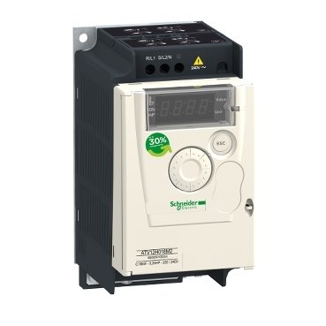
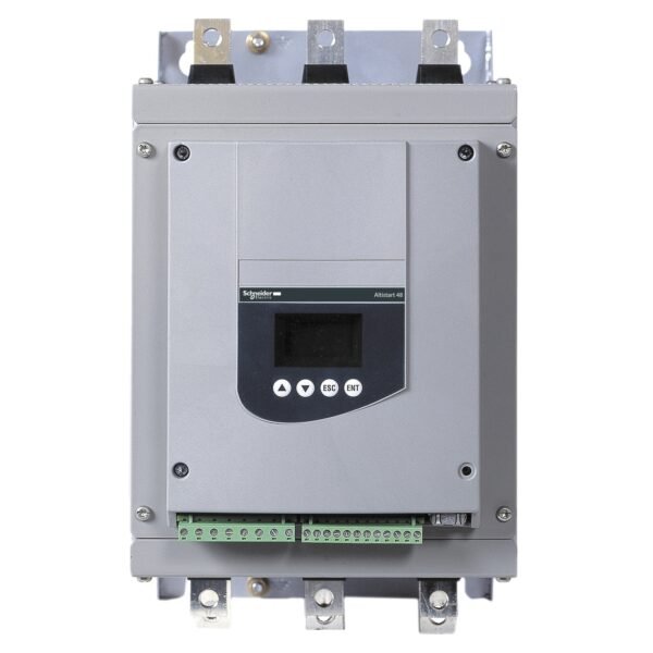
Schneider ATV12H018M2 | variable speed drive ATV12 – 0.18kW – 0.25hp – 200..240V – 1ph
Schneider ATV12H018M2 | variable speed drive ATV12 – 0.18kW – 0.25hp – 200..240V – 1ph
Original price was: EGP 15,845.09.EGP 8,714.80Current price is: EGP 8,714.80.
Description
Schneider ATV12H018M2 | variable speed drive ATV12 – 0.18kW – 0.25hp – 200..240V – 1ph
Schneider ATV12H018M2: The Ultimate Variable Speed Drive for Industrial Applications
Introduction
In today’s industrial landscape, the need for precise motor control and energy efficiency is paramount. The Schneider ATV12H018M2 variable speed drive is a solution designed to meet these needs. But what exactly makes this drive stand out, and how can it benefit your operations?
What is Schneider ATV12H018M2?
it is a versatile and efficient variable speed drive designed for controlling motor speeds in various applications. Known for its reliability and user-friendly interface, it is an essential tool for optimizing motor performance.
Technical Specifications
Understanding the technical specifications of it is crucial for its optimal use. Here are some key aspects:
- Power Rating: It has a power rating of 0.18 kW, suitable for small to medium-sized motors.
- Input and Output Voltage: Operates at an input voltage of 200-240V and provides a similar output voltage range.
- Frequency Range: Supports a frequency range of 0.5 to 200 Hz, offering flexibility in motor speed control.
Benefits of Using Schneider ATV12H018M2
Why should you choose it for your motor control needs? Here are some compelling benefits:
- Enhanced Motor Control: Provides precise control over motor speeds, ensuring smooth operation.
- Energy Efficiency: Optimizes motor performance to reduce energy consumption and operational costs.
- Easy Integration: Designed for seamless integration with existing systems, minimizing installation hassle.
Installation and Setup
Installing it is straightforward but requires attention to detail:
Pre-installation Considerations
Ensure you have all necessary tools and understand the motor and system requirements where the drive will be installed.
Step-by-Step Installation Guide
- Turn off Power: Always start by shutting down the power to avoid any accidents.
- Mount the Device: Secure the drive in an accessible location.
- Connect Wires: Follow the wiring diagram to connect the device correctly.
- Power Up: Once everything is connected, turn the power back on and verify the installation.
Safety Precautions
Adhere to safety guidelines to prevent electrical hazards during installation.
User Interface and Connectivity
The user interface and connectivity options of it are designed for ease of use:
- Display and Control Features: It features a clear display and intuitive controls for easy operation.
- Connectivity Options: Ensures seamless integration with other industrial control systems and networks.
Applications of Schneider ATV12H018M2
The versatility of the Schneider ATV12H018M2 makes it suitable for various applications:
Industrial Usage
Ideal for manufacturing plants, automation systems, and conveyor belts, ensuring reliable motor control.
Commercial Usage
Perfect for HVAC systems, elevators, and other commercial motor-driven applications.
Specific Use Cases
Suitable for pumps, fans, and other critical processes requiring precise motor speed control.
Additional information
| brands | Schneider Electric |
|---|
Specifications
| Range of product | Altivar 12 |
|---|---|
| product or component type | Variable speed drive |
| Product specific application | Simple machine |
| mounting mode | Cabinet mount |
| Communication port protocol | Modbus |
| Supply frequency | 50/60 Hz +/- 5 % |
| [Us] rated supply voltage | 200...240 V - 15...10 % |
| Nominal output current | 1.4 A |
| Motor power hp | 0.25 hp |
| Motor power kW | 0.18 kW |
| Motor power hp | 0.25 hp |
| EMC filter | Integrated |
| IP degree of protection | IP20 |
| Discrete input number | 4 |
|---|---|
| Discrete output number | 2 |
| Analogue input number | 1 |
| Analogue output number | 1 |
| Relay output number | 1 |
| Physical interface | 2-wire RS 485 |
| Connector type | 1 RJ45 |
| Continuous output current | 1.4 A at 4 kHz |
| Method of access | Server Modbus serial |
| Speed drive output frequency | 0.5…400 Hz |
| Speed range | 1…20 |
| Sampling duration | 20 ms, tolerance +/- 1 ms for logic input 10 ms for analogue input |
| Linearity error | +/- 0.3 % of maximum value for analogue input |
| Frequency resolution | Analog input: converter A/D, 10 bits Display unit: 0.1 Hz |
| Time constant | 20 ms +/- 1 ms for reference change |
| Transmission rate | 9.6 kbit/s 19.2 kbit/s 38.4 kbit/s |
| Transmission frame | RTU |
| Number of addresses | 1…247 |
| Data format | 8 bits, configurable odd, even or no parity |
| Communication service | Read holding registers (03) 29 words Write single register (06) 29 words Write multiple registers (16) 27 words Read/write multiple registers (23) 4/4 words Read device identification (43) |
| Type of polarization | No impedance |
| 4 quadrant operation possible | False |
| Asynchronous motor control profile | Voltage/frequency ratio (V/f) Sensorless flux vector control Quadratic voltage/frequency ratio |
| Maximum output frequency | 4 kHz |
| Transient overtorque | 150…170 % of nominal motor torque depending on drive rating and type of motor |
| Acceleration and deceleration ramps | U Linear from 0 to 999.9 s S |
| Motor slip compensation | Preset in factory Adjustable |
| Switching frequency | 2...16 kHz adjustable 4...16 kHz with derating factor |
| Nominal switching frequency | 4 kHz |
| Braking to standstill | By DC injection |
| Brake chopper integrated | False |
| Line current | 3.4 A at 100 V (heavy duty) 2.8 A at 120 V (heavy duty) |
| Maximum input current | 2.8 A |
| Maximum output voltage | 240 V |
| Apparent power | 0.7 kVA at 240 V (heavy duty) |
| Maximum transient current | 2.1 A during 60 s (heavy duty) 2.3 A during 2 s (heavy duty) |
| Network frequency | 50...60 Hz |
| Relative symmetric network frequency tolerance | 5 % |
| Prospective line Isc | 1 kA |
| Base load current at high overload | 1.4 A |
| Power dissipation in W | Natural: 18.0 W |
| With safety function Safely Limited Speed (SLS) | False |
| With safety function Safe brake management (SBC/SBT) | False |
| With safety function Safe Operating Stop (SOS) | False |
| With safety function Safe Position (SP) | False |
| With safety function Safe programmable logic | False |
| With safety function Safe Speed Monitor (SSM) | False |
| With safety function Safe Stop 1 (SS1) | False |
| With sft fct Safe Stop 2 (SS2) | False |
| With safety function Safe torque off (STO) | False |
| With safety function Safely Limited Position (SLP) | False |
| With safety function Safe Direction (SDI) | False |
| Protection type | Line supply overvoltage Line supply undervoltage Overcurrent between output phases and earth Overheating protection Short-circuit between motor phases Against input phase loss in three-phase Thermal motor protection via the drive by continuous calculation of I²t |
| Tightening torque | 0.8 N.m |
| Insulation | Electrical between power and control |
| Quantity per set | Set of 1 |
| Width | 72 mm |
| Height | 143 mm |
| Depth | 102.2 mm |
| net weight | 0.7 kg |
| Operating altitude | > 1000...2000 m with current derating 1 % per 100 m <= 1000 m without derating |
|---|---|
| Operating position | Vertical +/- 10 degree |
| Product certifications | NOM CSA C-Tick UL GOST RCM KC |
| marking | CE |
| Standards | UL 508C UL 618000-5-1 IEC 61800-5-1 IEC 61800-3 |
| Assembly style | On base plate |
| Electromagnetic compatibility | Electrical fast transient/burst immunity test level 4 conforming to IEC 61000-4-4 Electrostatic discharge immunity test level 3 conforming to IEC 61000-4-2 Immunity to conducted disturbances level 3 conforming to IEC 61000-4-6 Radiated radio-frequency electromagnetic field immunity test level 3 conforming to IEC 61000-4-3 Surge immunity test level 3 conforming to IEC 61000-4-5 Voltage dips and interruptions immunity test conforming to IEC 61000-4-11 |
| Environmental class (during operation) | Class 3C3 according to IEC 60721-3-3 Class 3S2 according to IEC 60721-3-3 |
| Maximum acceleration under shock impact (during operation) | 150 m/s² at 11 ms |
| Maximum acceleration under vibrational stress (during operation) | 10 m/s² at 13...200 Hz |
| Maximum deflection under vibratory load (during operation) | 1.5 mm at 2...13 Hz |
| Overvoltage category | Class III |
| Regulation loop | Adjustable PID regulator |
| Electromagnetic emission | Radiated emissions environment 1 category C2 conforming to IEC 61800-3 2...16 kHz shielded motor cable Conducted emissions with integrated EMC filter environment 1 category C1 conforming to IEC 61800-3 2, 4, 8, 12 and 16 kHz shielded motor cable <5 m Conducted emissions with integrated EMC filter environment 1 category C2 conforming to IEC 61800-3 2...12 kHz shielded motor cable <5 m Conducted emissions with integrated EMC filter environment 1 category C2 conforming to IEC 61800-3 2, 4 and 16 kHz shielded motor cable <10 m Conducted emissions with additional EMC filter environment 1 category C1 conforming to IEC 61800-3 4...12 kHz shielded motor cable <20 m Conducted emissions with additional EMC filter environment 1 category C2 conforming to IEC 61800-3 4...12 kHz shielded motor cable <50 m Conducted emissions with additional EMC filter environment 2 category C3 conforming to IEC 61800-3 4...12 kHz shielded motor cable <50 m |
| Vibration resistance | 1 gn (f = 13…200 Hz) conforming to IEC 60068-2-6 1.5 mm peak to peak (f = 3…13 Hz) - drive unmounted on symmetrical DIN rail - conforming to IEC 60068-2-6 |
| Shock resistance | 15 gn conforming to IEC 60068-2-27 for 11 ms |
| Relative humidity | 5…95 % without condensation conforming to IEC 60068-2-3 5…95 % without dripping water conforming to IEC 60068-2-3 |
| Noise level | 0 dB |
| Pollution degree | 2 |
| Ambient air transport temperature | -25…70 °C |
| Ambient air temperature for operation | -10…40 °C without derating 40…60 °C with current derating 2.2 % per °C |
| Ambient air temperature for storage | -25…70 °C |
| Unit Type of Package 1 | PCE |
|---|---|
| Number of Units in Package 1 | 1 |
| Package 1 Height | 11.500 cm |
| Package 1 Width | 18.600 cm |
| Package 1 Length | 19.500 cm |
| Package 1 Weight | 887.000 g |
| Unit Type of Package 2 | S06 |
| Number of Units in Package 2 | 45 |
| Package 2 Height | 75.000 cm |
| Package 2 Width | 60.000 cm |
| Package 2 Length | 80.000 cm |
| Package 2 Weight | 52.780 kg |
| Warranty | 18 months |
|---|


Reviews
There are no reviews yet.