
No products in the cart.
-45%On Sale
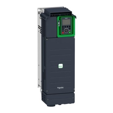
Schneider ATV930D30N4 | variable speed drive, ATV930, 30kW, 400/480V, with braking unit, IP21
Schneider ATV930D30N4 | variable speed drive, ATV930, 30kW, 400/480V, with braking unit, IP21
Original price was: EGP 4,047,456.00.EGP 2,226,101.00Current price is: EGP 2,226,101.00.
Description
Introduction
The Schneider ATV930D30N4 is a high-performance variable speed drive designed to optimize industrial processes. Its advanced features and durable construction make it a vital component in a wide range of industrial applications, ensuring both efficiency and reliability.
What is the Schneider ATV930D30N4?
it is part of the Altivar Process 930 series, known for its exceptional performance and energy efficiency. This model stands out for its versatility and scalability, suitable for a broad spectrum of industrial uses. Compared to other models in the ATV930 series, it offers enhanced capabilities tailored to meet the rigorous demands of industrial environments.
Key Features of the Schneider ATV930D30N4
Energy Efficiency
it is engineered for superior energy efficiency, significantly reducing energy consumption. This not only lowers operational costs but also minimizes the environmental impact, aligning with sustainability objectives.
Flexibility and Scalability
This model is highly flexible and scalable, easily adapting to various industrial needs. Its modular design allows for seamless integration into existing systems and scalability as operational demands increase.
Robust Design
Constructed to endure challenging industrial conditions, it features a robust design that ensures durability and longevity. This minimizes downtime and maintenance costs, contributing to sustained productivity.
Technical Specifications
Power Ratings
it offers a range of power ratings to meet diverse application requirements, ensuring it can support various industrial processes efficiently.
Input and Output Voltage
It supports multiple input and output voltage ranges, providing the flexibility needed for different industrial settings.
Frequency Range
Operating within a wide frequency range, it is suitable for various types of machinery and equipment, enhancing its versatility.
Applications of the Schneider ATV930D30N4
Industrial Automation
In industrial automation, it plays a pivotal role in improving the efficiency and performance of automated systems, ensuring precise control and smooth operation of machinery.
HVAC Systems
it is widely utilized in HVAC systems, optimizing energy use and maintaining consistent performance, which is crucial for climate control and ventilation systems.
Water and Wastewater Management
In water and wastewater management, it ensures efficient and reliable operation of pumps and other equipment, contributing to effective resource management and sustainability.
Advantages of Using Schneider ATV930D30N4
Cost Savings
By significantly reducing energy consumption and maintenance costs, the ATV930D30N4 offers considerable cost savings over its lifecycle, making it a cost-effective solution for industries.
Enhanced Operational Efficiency
With precise control and advanced features, the ATV930D30N4 enhances operational efficiency, ensuring smooth and uninterrupted industrial processes.
Reduced Environmental Impact
Its energy-efficient design helps in reducing the environmental impact of industrial operations, supporting sustainability goals and compliance with environmental regulations.
Installation and Setup
Pre-Installation Considerations
Before installing the ATV930D30N4, it is essential to consider factors such as the installation environment and compatibility with existing systems to ensure a successful setup.
Step-by-Step Installation Guide
- Prepare the installation site.
- Securely mount the drive.
- Connect the electrical wiring according to the manual’s instructions.
- Configure the drive settings according to the specific application requirements.
Initial Setup and Configuration
Post-installation, the initial setup involves configuring the drive parameters to match the application’s needs, ensuring optimal performance and efficiency.
Maintenance and Troubleshooting
Routine Maintenance Tips
Regular maintenance is vital for the longevity and optimal performance of the ATV930D30N4. This includes periodic inspections, cleaning, and ensuring all connections are secure.
Common Issues and Solutions
Common issues with the ATV930D30N4 include overheating and communication errors. These can typically be resolved through troubleshooting steps provided in the user manual or by contacting Schneider’s technical support.
Support and Resources
Schneider offers extensive support and resources for the ATV930D30N4, including technical support, online resources, and comprehensive manuals to assist with maintenance and troubleshooting.
Energy Management with ATV930D30N4
Energy Monitoring Capabilities
The ATV930D30N4 features built-in energy monitoring capabilities, allowing users to track and optimize energy usage effectively.
Integration with Energy Management Systems
It can be integrated with broader energy management systems, providing a comprehensive solution for monitoring and managing energy efficiency.
Benefits of Energy Management
Effective energy management with the ATV930D30N4 leads to reduced energy costs, improved operational efficiency, and enhanced sustainability, making it an excellent choice for industries focused on energy conservation.
Integration with Other Systems
Compatibility with Existing Systems
The ATV930D30N4 is designed for compatibility with a wide range of existing systems, ensuring seamless integration without extensive modifications.
Communication Protocols
Supporting various communication protocols, including Modbus and Ethernet, the ATV930D30N4 facilitates easy integration and communication with other systems.
Case Studies of Successful Integrations
Numerous case studies demonstrate the successful integration of the ATV930D30N4 into different industrial environments, highlighting its versatility and effectiveness in improving operational efficiency.
Safety Features
Built-In Safety Mechanisms
The ATV930D30N4 includes built-in safety mechanisms such as overload protection and fault detection, ensuring safe operation in various industrial settings.
Compliance with Safety Standards
Complying with international safety standards, the ATV930D30N4 provides assurance of its reliability and safety in industrial applications.
User Safety Tips
Users should follow safety guidelines provided in the manual to ensure safe operation and maintenance of the drive, minimizing the risk of accidents and equipment damage.
Additional information
| brands | Schneider Electric |
|---|
Specifications
| Range of product | Altivar Process ATV900 |
|---|---|
| Device application | Industrial application |
| product or component type | Variable speed drive |
| product destination | Asynchronous motors Synchronous motors |
| Product specific application | Process for industrial |
| variant | With braking chopper Standard version |
| Network number of phases | 3 phases |
| mounting mode | Wall mount |
| Communication port protocol | Modbus serial EtherNet/IP Modbus TCP |
| [Us] rated supply voltage | 380...480 V - 15...10 % |
| Motor power kW | 30.0 kW for normal duty 22.0 kW for heavy duty |
| Continuous output current | 61.5 A at 4 kHz for normal duty 46.3 A at 4 kHz for heavy duty |
| EMC filter | Integrated With EMC plate option |
| IP degree of protection | IP21 |
| Degree of protection | UL type 1 |
| option module | Slot A: communication module for Profibus DP V1 Slot A: communication module for PROFINET Slot A: communication module for DeviceNet Slot A: communication module for EtherCAT Slot A: communication module for CANopen daisy chain RJ45 Slot A: communication module for CANopen SUB-D 9 Slot A: communication module for CANopen screw terminals Slot A/slot B/slot C: digital and analog I/O extension module Slot A/slot B/slot C: output relay extension module Slot B: 5/12 V digital encoder interface module Slot B: analog encoder interface module Slot B: resolver encoder interface module communication module for Ethernet Powerlink |
| Discrete input logic | 16 preset speeds |
| Asynchronous motor control profile | Constant torque standard Variable torque standard Optimized torque mode |
| Synchronous motor control profile | Permanent magnet motor Synchronous reluctance motor |
| Maximum output frequency | 599 Hz |
| Switching frequency | 2...16 kHz adjustable 4...16 kHz with derating factor |
| Nominal switching frequency | 4 kHz |
| Line current | 53.3 A at 380 V (normal duty) 40.5 A at 380 V (heavy duty) 45.9 A at 480 V (normal duty) 35.8 A at 480 V (heavy duty) |
| Apparent power | 38.1 kVA at 480 V (normal duty) 29.8 kVA at 480 V (heavy duty) |
| Maximum transient current | 73.8 A during 60 s (normal duty) 69.5 A during 60 s (heavy duty) |
| Network frequency | 50...60 Hz |
| Prospective line Isc | 50 kA |
| Discrete input number | 10 |
|---|---|
| Discrete input type | DI1...DI8 programmable, 24 V DC (<= 30 V), impedance: 3.5 kOhm DI7, DI8 programmable as pulse input: 0…30 kHz, 24 V DC (<= 30 V) STOA, STOB safe torque off, 24 V DC (<= 30 V), impedance: > 2.2 kOhm |
| Discrete output number | 2 |
| Discrete output type | Logic output DQ+ 0…1 kHz <= 30 V DC 100 mA Programmable as pulse output DQ+ 0…30 kHz <= 30 V DC 20 mA Logic output DQ- 0…1 kHz <= 30 V DC 100 mA |
| Analogue input number | 3 |
| Analogue input type | AI1, AI2, AI3 software-configurable voltage: 0...10 V DC, impedance: 30 kOhm, resolution 12 bits AI1, AI2, AI3 software-configurable current: 0...20 mA/4...20 mA, impedance: 250 Ohm, resolution 12 bits |
| Analogue output number | 2 |
| Analogue output type | Software-configurable voltage AQ1, AQ2: 0...10 V DC impedance 470 Ohm, resolution 10 bits Software-configurable current AQ1, AQ2: 0...20 mA impedance 500 Ohm, resolution 10 bits |
| Relay output number | 3 |
| Relay output type | Configurable relay logic R1: fault relay NO/NC electrical durability 100000 cycles Configurable relay logic R2: sequence relay NO electrical durability 1000000 cycles Configurable relay logic R3: sequence relay NO electrical durability 1000000 cycles |
| Maximum switching current | Relay output R1 on resistive load, cos phi = 1: 3 A at 250 V AC Relay output R1 on resistive load, cos phi = 1: 3 A at 30 V DC Relay output R1 on inductive load, cos phi = 0.4 and L/R = 7 ms: 2 A at 250 V AC Relay output R1 on inductive load, cos phi = 0.4 and L/R = 7 ms: 2 A at 30 V DC Relay output R2, R3 on resistive load, cos phi = 1: 5 A at 250 V AC Relay output R2, R3 on resistive load, cos phi = 1: 5 A at 30 V DC Relay output R2, R3 on inductive load, cos phi = 0.4 and L/R = 7 ms: 2 A at 250 V AC Relay output R2, R3 on inductive load, cos phi = 0.4 and L/R = 7 ms: 2 A at 30 V DC |
| Minimum switching current | Relay output R1, R2, R3: 5 mA at 24 V DC |
| Physical interface | Ethernet 2-wire RS 485 |
| Connector type | 2 RJ45 1 RJ45 |
| Method of access | Slave Modbus TCP |
| Transmission rate | 10, 100 Mbits 4.8 kbps 9600 bit/s 19200 bit/s |
| Transmission frame | RTU |
| Number of addresses | 1…247 |
| Data format | 8 bits, configurable odd, even or no parity |
| Type of polarization | No impedance |
| 4 quadrant operation possible | True |
| Acceleration and deceleration ramps | Linear adjustable separately from 0.01...9999 s |
| Motor slip compensation | Can be suppressed Automatic whatever the load Adjustable Not available in permanent magnet motor law |
| Braking to standstill | By DC injection |
| Brake chopper integrated | True |
| Maximum input current | 53.3 A |
| Maximum output voltage | 480.0 V |
| Relative symmetric network frequency tolerance | 5 % |
| Base load current at high overload | 46.3 A |
| Base load current at low overload | 61.5 A |
| Power dissipation in W | Natural convection: 93 W at 380 V, switching frequency 4 kHz Forced convection: 640 W at 380 V, switching frequency 4 kHz |
| With safety function Safely Limited Speed (SLS) | True |
| With safety function Safe brake management (SBC/SBT) | True |
| With safety function Safe Operating Stop (SOS) | False |
| With safety function Safe Position (SP) | False |
| With safety function Safe programmable logic | False |
| With safety function Safe Speed Monitor (SSM) | False |
| With safety function Safe Stop 1 (SS1) | True |
| With sft fct Safe Stop 2 (SS2) | False |
| With safety function Safe torque off (STO) | True |
| With safety function Safely Limited Position (SLP) | False |
| With safety function Safe Direction (SDI) | False |
| Protection type | Thermal protection: motor Safe torque off: motor Motor phase break: motor Thermal protection: drive Safe torque off: drive Overheating: drive Overcurrent between output phases and earth: drive Overload of output voltage: drive Short-circuit protection: drive Motor phase break: drive Overvoltages on the DC bus: drive Line supply overvoltage: drive Line supply undervoltage: drive Line supply phase loss: drive Overspeed: drive Break on the control circuit: drive |
| Quantity per set | 1 |
| Width | 226 mm |
| Height | 673 mm |
| Depth | 274 mm |
| net weight | 28 kg |
| Electrical connection | Control: screw terminal 0.5...1.5 mm²/AWG 20...AWG 16 Line side: screw terminal 25...50 mm²/AWG 4...AWG 1 Motor: screw terminal 25...50 mm²/AWG 4...AWG 1 DC bus: screw terminal 25...50 mm²/AWG 4...AWG 1 |
| Transmission rate | 10/100 Mbit/s for Ethernet IP/Modbus TCP 4.8, 9.6, 19.2, 38.4 kbit/s for Modbus serial |
| Exchange mode | Half duplex, full duplex, autonegotiation Ethernet IP/Modbus TCP |
| Data format | 8 bits, configurable odd, even or no parity for Modbus serial |
| Type of polarization | No impedance for Modbus serial |
| Number of addresses | 1…247 for Modbus serial |
| Supply | External supply for digital inputs: 24 V DC (19…30 V), <1.25 mA, protection type: overload and short-circuit protection Internal supply for reference potentiometer (1 to 10 kOhm): 10.5 V DC +/- 5 %, <10 mA, protection type: overload and short-circuit protection Internal supply for digital inputs and STO: 24 V DC (21…27 V), <200 mA, protection type: overload and short-circuit protection |
| Local signalling | Local diagnostic: 3 LED (mono/dual colour) Embedded communication status: 5 LED (dual colour) Communication module status: 2 LED (dual colour) Presence of voltage: 1 LED (red) |
| Input compatibility | DI1...DI8: discrete input level 1 PLC conforming to IEC 61131-2 DI7, DI8: pulse input level 1 PLC conforming to IEC 65A-68 STOA, STOB: discrete input level 1 PLC conforming to IEC 61131-2 |
| Discrete input logic | Positive logic (source) (DI1...DI8), < 5 V (state 0), > 11 V (state 1) Negative logic (sink) (DI1...DI8), > 16 V (state 0), < 10 V (state 1) Positive logic (source) (DI7, DI8), < 0.6 V (state 0), > 2.5 V (state 1) Positive logic (source) (STOA, STOB), < 5 V (state 0), > 11 V (state 1) |
| Sampling duration | 2 ms +/- 0.5 ms (DI1...DI8) - discrete input 5 ms +/- 1 ms (DI7, DI8) - pulse input 1 ms +/- 1 ms (AI1, AI2, AI3) - analog input 5 ms +/- 1 ms (AQ1, AQ2) - analog output |
| Accuracy | +/- 0.6 % AI1, AI2, AI3 for a temperature variation 60 °C analog input +/- 1 % AQ1, AQ2 for a temperature variation 60 °C analog output |
| Linearity error | AI1, AI2, AI3: +/- 0.15 % of maximum value for analog input AQ1, AQ2: +/- 0.2 % for analog output |
| Refresh time | Relay output (R1, R2, R3): 5 ms (+/- 0.5 ms) |
| Isolation | Between power and control terminals |
| Operating altitude | <= 1000 m without derating 1000...4800 m with current derating 1 % per 100 m |
|---|---|
| Operating position | Vertical +/- 10 degree |
| Product certifications | TÜV CSA UL |
| marking | CE |
| Standards | UL 508C IEC 61800-3 IEC 61800-5-1 IEC 61000-3-12 IEC 60721-3 IEC 61508 IEC 13849-1 |
| Maximum THDI | <48 % from 80...100 % of load conforming to IEC 61000-3-12 |
| Assembly style | Enclosed |
| Electromagnetic compatibility | Electrostatic discharge immunity test level 3 conforming to IEC 61000-4-2 Radiated radio-frequency electromagnetic field immunity test level 3 conforming to IEC 61000-4-3 Electrical fast transient/burst immunity test level 4 conforming to IEC 61000-4-4 1.2/50 µs - 8/20 µs surge immunity test level 3 conforming to IEC 61000-4-5 Conducted radio-frequency immunity test level 3 conforming to IEC 61000-4-6 |
| Environmental class (during operation) | Class 3C3 according to IEC 60721-3-3 Class 3S3 according to IEC 60721-3-3 |
| Maximum acceleration under shock impact (during operation) | 150 m/s² at 11 ms |
| Maximum acceleration under vibrational stress (during operation) | 10 m/s² at 13...200 Hz |
| Maximum deflection under vibratory load (during operation) | 1.5 mm at 2...13 Hz |
| Permitted relative humidity (during operation) | Class 3K5 according to EN 60721-3 |
| Volume of cooling air | 240 m3/h |
| Overvoltage category | III |
| Regulation loop | Adjustable PID regulator |
| Insulation resistance | > 1 MOhm 500 V DC for 1 minute to earth |
| Noise level | 71.5 dB conforming to 86/188/EEC |
| Vibration resistance | 1.5 mm peak to peak (f= 2…13 Hz) conforming to IEC 60068-2-6 1 gn (f= 13…200 Hz) conforming to IEC 60068-2-6 |
| Shock resistance | 15 gn for 11 ms conforming to IEC 60068-2-27 |
| Environmental characteristic | Chemical pollution resistance class 3C3 conforming to IEC 60721-3-3 Dust pollution resistance class 3S3 conforming to IEC 60721-3-3 |
| Relative humidity | 5…95 % without condensation conforming to IEC 60068-2-3 |
| Ambient air temperature for operation | -15…50 °C (without derating) 50…60 °C (with derating factor) |
| Noise level | 71.5 dB |
| Pollution degree | 2 |
| Ambient air transport temperature | -40…70 °C |
| Ambient air temperature for storage | -40…70 °C |
| Unit Type of Package 1 | PCE |
|---|---|
| Number of Units in Package 1 | 1 |
| Package 1 Height | 50.0 cm |
| Package 1 Width | 34.5 cm |
| Package 1 Length | 84.5 cm |
| Package 1 Weight | 28.7 kg |


Reviews
There are no reviews yet.