
No products in the cart.
-46%On Sale
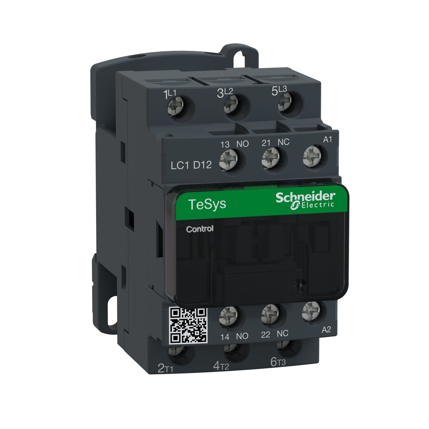

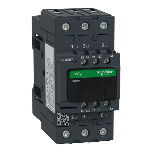
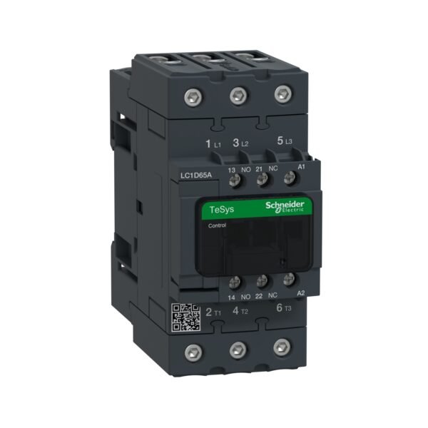
Schneider LC1D12M7 Contactor | TeSys D contactor – 3P(3 NO) – AC-3 – <= 440 V 12 A – 220 V AC coil
Schneider LC1D12M7 Contactor
Original price was: EGP 3,239.82.EGP 1,752.90Current price is: EGP 1,752.90.
Description
Schneider LC1D12M7 Contactor: Enhancing Electrical System Efficiency
1. Introduction to Schneider LC1D12M7 Contactor
In the realm of electrical engineering, ensuring seamless power distribution and control is paramount. One crucial component facilitating this is the contactor. Among the myriad options available in the market, is stands out for its reliability, efficiency, and versatile applications.
2. Understanding the Functionality of Contactors
What is a contactor?
A contactor is an electromechanical device used to make or break electrical connections. It functions akin to a relay but is specifically designed to handle higher current loads.
Role of contactors in electrical systems
Contactors play a pivotal role in controlling the flow of electricity within electrical systems. They are often employed in circuits where frequent switching of loads is required, ensuring smooth operation and preventing overload.
3. Features
Specifications and ratings
is engineered to meet the demands of various industrial and commercial applications. With a rated operational current of 12A and a coil voltage of 24V AC, it offers optimal performance under diverse operating conditions.
Design and construction
Crafted with precision engineering, the LC1D12M7 boasts robust construction and durable materials, ensuring longevity and reliability even in harsh environments.
4. Applications
Industrial applications
From motor control to lighting systems, the Schneider LC1D12M7 Contactor finds extensive use across various industrial sectors, including manufacturing, automation, and energy management.
Commercial applications
In commercial settings such as office buildings, retail spaces, and healthcare facilities, the LC1D12M7 plays a crucial role in HVAC (Heating, Ventilation, and Air Conditioning) systems, elevators, and lighting control.
5. Advantages
Efficiency and reliability
With its robust design and advanced features, the Schneider LC1D12M7 ensures efficient power distribution and seamless operation, minimizing downtime and maximizing productivity.
Safety features
Equipped with integrated protection mechanisms, including overload and short-circuit protection, the LC1D12M7 prioritizes safety, safeguarding both equipment and personnel from potential hazards.
6. Installation Guide
Pre-installation checks
Before installing the LC1D12M7 Contactor, it is essential to conduct thorough inspections, ensuring compatibility with the existing electrical system and adherence to safety standards.
Wiring instructions
Proper wiring is critical for the optimal performance of the LC1D12M7 Contactor. Following the manufacturer’s guidelines and industry best practices is imperative to prevent issues such as overheating and electrical faults.
7. Maintenance Tips
Regular inspections
Scheduled maintenance routines, including visual inspections and testing of critical components, help identify potential issues early on, ensuring uninterrupted operation and prolonging the lifespan of the contactor.
Troubleshooting common issues
Familiarizing oneself with common issues such as contact welding or coil failures empowers users to troubleshoot and resolve minor issues promptly, minimizing downtime and avoiding costly repairs.
Additional information
| brands | Schneider Electric |
|---|
Specifications
| Range of product | TeSys Deca |
|---|---|
| Product or component type | Contactor |
| Device short name | LC1D |
| Contactor application | Resistive load Motor control |
| Utilisation category | AC-4 AC-1 AC-3 AC-3e |
| Poles description | 3P |
| [Ue] rated operational voltage | Power circuit: <= 690 V AC 25...400 Hz Power circuit: <= 300 V DC |
| [Ie] rated operational current | 25 A (at <60 °C) at <= 440 V AC AC-1 for power circuit 12 A (at <60 °C) at <= 440 V AC AC-3 for power circuit 12 A (at <60 °C) at <= 440 V AC AC-3e for power circuit |
| [Uc] control circuit voltage | 220 V AC 50/60 Hz |
| Motor power kW | 3 kW at 220...230 V AC 50/60 Hz (AC-3) 5.5 kW at 380...400 V AC 50/60 Hz (AC-3) 5.5 kW at 415...440 V AC 50/60 Hz (AC-3) 7.5 kW at 500 V AC 50/60 Hz (AC-3) 7.5 kW at 660...690 V AC 50/60 Hz (AC-3) 3.7 kW at 400 V AC 50/60 Hz (AC-4) 3 kW at 220...230 V AC 50/60 Hz (AC-3e) 5.5 kW at 380...400 V AC 50/60 Hz (AC-3e) 5.5 kW at 415...440 V AC 50/60 Hz (AC-3e) 7.5 kW at 500 V AC 50/60 Hz (AC-3e) 7.5 kW at 660...690 V AC 50/60 Hz (AC-3e) |
|---|---|
| Motor power hp | 0.5 hp at 115 V AC 50/60 Hz for 1 phase motors 2 hp at 230/240 V AC 50/60 Hz for 1 phase motors 3 hp at 200/208 V AC 50/60 Hz for 3 phases motors 3 hp at 230/240 V AC 50/60 Hz for 3 phases motors 7.5 hp at 460/480 V AC 50/60 Hz for 3 phases motors 10 hp at 575/600 V AC 50/60 Hz for 3 phases motors |
| Compatibility code | LC1D |
| Pole contact composition | 3 NO |
| Protective cover | With |
| [Ith] conventional free air thermal current | 25 A (at 60 °C) for power circuit 10 A (at 60 °C) for signalling circuit |
| Irms rated making capacity | 250 A at 440 V for power circuit conforming to IEC 60947 140 A AC for signalling circuit conforming to IEC 60947-5-1 250 A DC for signalling circuit conforming to IEC 60947-5-1 |
| Rated breaking capacity | 250 A at 440 V for power circuit conforming to IEC 60947 |
| [Icw] rated short-time withstand current | 105 A 40 °C - 10 s for power circuit 210 A 40 °C - 1 s for power circuit 30 A 40 °C - 10 min for power circuit 61 A 40 °C - 1 min for power circuit 100 A - 1 s for signalling circuit 120 A - 500 ms for signalling circuit 140 A - 100 ms for signalling circuit |
| Associated fuse rating | 10 A gG for signalling circuit conforming to IEC 60947-5-1 40 A gG at <= 690 V coordination type 1 for power circuit 25 A gG at <= 690 V coordination type 2 for power circuit |
| Average impedance | 2.5 mOhm - Ith 25 A 50 Hz for power circuit |
| Power dissipation per pole | 0.36 W AC-3 1.56 W AC-1 0.36 W AC-3e |
| [Ui] rated insulation voltage | Power circuit: 690 V conforming to IEC 60947-4-1 Power circuit: 600 V CSA certified Power circuit: 600 V UL certified Signalling circuit: 690 V conforming to IEC 60947-1 Signalling circuit: 600 V CSA certified Signalling circuit: 600 V UL certified |
| Overvoltage category | III |
| Pollution degree | 3 |
| [Uimp] rated impulse withstand voltage | 6 kV conforming to IEC 60947 |
| Safety reliability level | B10d = 1369863 cycles contactor with nominal load conforming to EN/ISO 13849-1 B10d = 20000000 cycles contactor with mechanical load conforming to EN/ISO 13849-1 |
| Mechanical durability | 15 Mcycles |
| Electrical durability | 2 Mcycles 12 A AC-3 at Ue <= 440 V 0.8 Mcycles 25 A AC-1 at Ue <= 440 V 2 Mcycles 12 A AC-3e at Ue <= 440 V |
| Control circuit type | AC at 50/60 Hz standard |
| Coil technology | Without built-in suppressor module |
| Control circuit voltage limits | 0.3...0.6 Uc (-40…70 °C):drop-out AC 50/60 Hz 0.8...1.1 Uc (-40…60 °C):operational AC 50 Hz 0.85...1.1 Uc (-40…60 °C):operational AC 60 Hz 1...1.1 Uc (60…70 °C):operational AC 50/60 Hz |
| Inrush power in VA | 70 VA 60 Hz cos phi 0.75 (at 20 °C) 70 VA 50 Hz cos phi 0.75 (at 20 °C) |
| Hold-in power consumption in VA | 7.5 VA 60 Hz cos phi 0.3 (at 20 °C) 7 VA 50 Hz cos phi 0.3 (at 20 °C) |
| Heat dissipation | 2…3 W at 50/60 Hz |
| Operating time | 12...22 ms closing 4...19 ms opening |
| Maximum operating rate | 3600 cyc/h 60 °C |
| Maximum operating rate | 3600 cyc/h at 60 °C |
| Connections - terminals | Power circuit: screw clamp terminals 1 1…4 mm² - cable stiffness: flexible without cable end Power circuit: screw clamp terminals 2 1…4 mm² - cable stiffness: flexible without cable end Power circuit: screw clamp terminals 1 1…4 mm² - cable stiffness: flexible with cable end Power circuit: screw clamp terminals 2 1…2.5 mm² - cable stiffness: flexible with cable end Power circuit: screw clamp terminals 1 1…4 mm² - cable stiffness: solid without cable end Power circuit: screw clamp terminals 2 1…4 mm² - cable stiffness: solid without cable end Control circuit: screw clamp terminals 1 1…4 mm² - cable stiffness: flexible without cable end Control circuit: screw clamp terminals 2 1…4 mm² - cable stiffness: flexible without cable end Control circuit: screw clamp terminals 1 1…4 mm² - cable stiffness: flexible with cable end Control circuit: screw clamp terminals 2 1…2.5 mm² - cable stiffness: flexible with cable end Control circuit: screw clamp terminals 1 1…4 mm² - cable stiffness: solid without cable end Control circuit: screw clamp terminals 2 1…4 mm² - cable stiffness: solid without cable end |
| Tightening torque | Power circuit: 1.7 N.m - on screw clamp terminals - with screwdriver flat Ø 6 mm Power circuit: 1.7 N.m - on screw clamp terminals - with screwdriver Philips No 2 Control circuit: 1.7 N.m - on screw clamp terminals - with screwdriver flat Ø 6 mm Control circuit: 1.7 N.m - on screw clamp terminals - with screwdriver Philips No 2 Control circuit: 1.7 N.m - on screw clamp terminals - with screwdriver pozidriv No 2 Power circuit: 1.7 N.m - on screw clamp terminals - with screwdriver pozidriv No 2 |
| Auxiliary contact composition | 1 NO + 1 NC |
| Auxiliary contacts type | type mechanically linked 1 NO + 1 NC conforming to IEC 60947-5-1 type mirror contact 1 NC conforming to IEC 60947-4-1 |
| Signalling circuit frequency | 25...400 Hz |
| Minimum switching voltage | 17 V for signalling circuit |
| Minimum switching current | 5 mA for signalling circuit |
| Insulation resistance | > 10 MOhm for signalling circuit |
| Non-overlap time | 1.5 ms on de-energisation between NC and NO contact 1.5 ms on energisation between NC and NO contact |
| Mounting support | Rail Plate |
| Standards | CSA C22.2 No 14 EN 60947-4-1 EN 60947-5-1 IEC 60947-4-1 IEC 60947-5-1 UL 60947-4-1 IEC 60335-1:Clause 30.2 IEC 60335-2-40:Annex JJ UL 60335-2-40:Annex JJ CSA C22.2 No 60947-4-1 |
|---|---|
| Product certifications | UL CCC CSA Marine UKCA EAC CB Scheme |
| IP degree of protection | IP20 front face conforming to IEC 60529 |
| Protective treatment | TH conforming to IEC 60068-2-30 |
| Climatic withstand | conforming to IACS E10 exposure to damp heat conforming to IEC 60947-1 Annex Q category D exposure to damp heat |
| Permissible ambient air temperature around the device | -40…60 °C 60…70 °C with derating |
| Operating altitude | 0...3000 m |
| Fire resistance | 850 °C conforming to IEC 60695-2-1 |
| Flame retardance | V1 conforming to UL 94 |
| Mechanical robustness | Vibrations contactor open (2 Gn, 5...300 Hz) Vibrations contactor closed (4 Gn, 5...300 Hz) Shocks contactor open (10 Gn for 11 ms) Shocks contactor closed (15 Gn for 11 ms) |
| Height | 77 mm |
| Width | 45 mm |
| Depth | 86 mm |
| Net weight | 0.325 kg |
| Unit Type of Package 1 | PCE |
|---|---|
| Number of Units in Package 1 | 1 |
| Package 1 Height | 5.000 cm |
| Package 1 Width | 9.200 cm |
| Package 1 Length | 11.100 cm |
| Package 1 Weight | 352.000 g |
| Unit Type of Package 2 | S02 |
| Number of Units in Package 2 | 20 |
| Package 2 Height | 15.000 cm |
| Package 2 Width | 30.000 cm |
| Package 2 Length | 40.000 cm |
| Package 2 Weight | 7.367 kg |
| Warranty | 18 months |
|---|


Reviews
There are no reviews yet.