
No products in the cart.

Description
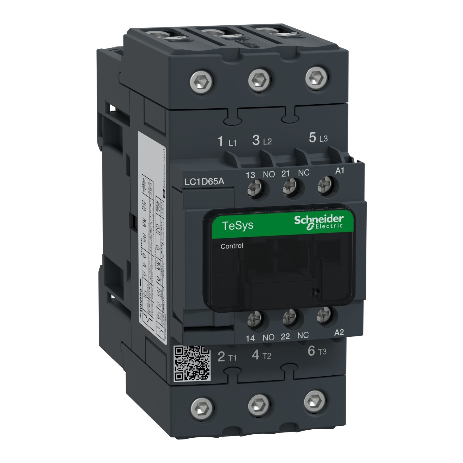
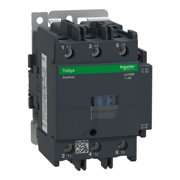
Schneider LC1D65AF7| TeSys D contactor – 3P(3 NO) – AC-3 – <= 440 V 65 A – 110 V AC 50/60 Hz coil
Schneider LC1D65AF7 Description
Introduction to Schneider LC1D65AF7
The Schneider LC1D65AF7 is a powerful and reliable contactor designed for various industrial applications. This article provides a comprehensive description of the LC1D65AF7, including its specifications, features, applications, advantages, and installation procedures.
Specifications of LC1D65AF7
The LC1D65AF7 is a three-pole contactor with a voltage rating of up to 690V AC and a current rating of 65A. It operates with a coil voltage of 24V AC/DC, providing flexibility in different electrical systems.
Features of Schneider LC1D65AF7
TeSys D Contactor
The LC1D65AF7 belongs to the TeSys D range of contactors, known for their high performance and reliability. It features robust construction and durable materials, ensuring long-term operation in harsh industrial environments.
Compact Design
Despite its high power handling capacity, the LC1D65AF7 boasts a compact and space-saving design. This makes it suitable for installations where space is limited, without compromising on performance.
Easy Installation
Installing the LC1D65AF7 is straightforward, thanks to its user-friendly design and clear labeling of terminals. It comes with detailed installation instructions, enabling electricians to set it up quickly and efficiently.
Applications of LC1D65AF7
The Schneider LC1D65AF7 is widely used in various industrial sectors, including:
- Industrial Machinery: It is commonly used in motor control circuits for controlling motors and other heavy-duty equipment.
- HVAC Systems: The LC1D65AF7 plays a crucial role in controlling the operation of heating, ventilation, and air conditioning systems.
- Lighting Control: It can be employed in lighting control panels for switching and controlling lighting circuits in commercial and industrial buildings.
Advantages of Using LC1D65AF7
Reliability
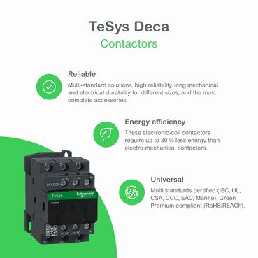
The LC1D65AF7 is built to withstand tough operating conditions, ensuring reliable performance even in demanding environments.
Energy Efficiency
With its efficient design and low power consumption, the LC1D65AF7 helps minimize energy wastage and reduce operational costs.
Safety Features
The contactor is equipped with various safety features, including overload protection and built-in surge suppression, ensuring the safety of both equipment and personnel.
Comparison with Other Contactors
Compared to traditional contactors, the LC1D65AF7 offers superior performance, reliability, and versatility, making it the preferred choice for many industrial applications.
Installation and Maintenance of LC1D65AF7
Wiring Procedures
Proper wiring is essential for the safe and reliable operation of the LC1D65AF7. Electricians should follow the manufacturer’s guidelines and wiring diagrams to ensure correct connections.
Safety Precautions
During installation and maintenance, proper safety precautions must be followed to prevent accidents and injuries. This includes de-energizing the circuit, using appropriate personal protective equipment, and following lockout/tagout procedures.
Maintenance Tips
Regular maintenance is key to prolonging the lifespan of the LC1D65AF7 and ensuring optimal performance. This includes periodic inspection, cleaning, and testing of the contactor and associated components.
Troubleshooting Common Issues
Despite its reliability, the LC1D65AF7 may encounter issues such as overheating, coil failure, or contact welding. Understanding these common issues and their causes is essential for effective troubleshooting and timely resolution.
Customer Reviews and Feedback
Customers who have used the Schneider LC1D65AF7 praise its reliability, performance, and ease of installation. Many have reported significant improvements in their industrial processes after switching to the LC1D65AF7.
Conclusion
In conclusion, the Schneider LC1D65AF7 is a high-quality contactor that offers superior performance, reliability, and safety features. Its compact design, easy installation, and versatile applications make it the ideal choice for various industrial needs.
Additional information
| brands | Schneider Electric |
|---|
Specifications
| Range | TeSys TeSys Deca |
|---|---|
| Range of product | TeSys Deca |
| Product or component type | Contactor |
| Device short name | LC1D |
| Contactor application | Resistive load Motor control |
| Utilisation category | AC-4 AC-1 AC-3 AC-3e |
| Poles description | 3P |
| [Ue] rated operational voltage | Power circuit: <= 690 V AC 25...400 Hz Power circuit: <= 300 V DC |
| [Ie] rated operational current | 80 A (at <60 °C) at <= 440 V AC AC-1 for power circuit 65 A (at <60 °C) at <= 440 V AC AC-3 for power circuit 65 A (at <60 °C) at <= 440 V AC AC-3e for power circuit |
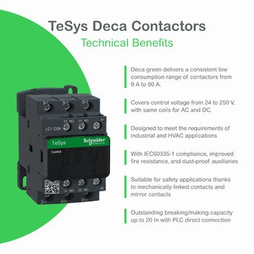
| [Uc] control circuit voltage | 110 V AC 50/60 Hz |
| Motor power kW | 11 kW at 400 V AC 50/60 Hz (AC-4) 18.5 kW at 220...230 V AC 50/60 Hz (AC-3) 30 kW at 380...400 V AC 50/60 Hz (AC-3) 37 kW at 500 V AC 50/60 Hz (AC-3) 37 kW at 660...690 V AC 50/60 Hz (AC-3) 18.5 kW at 220...230 V AC 50/60 Hz (AC-3e) 30 kW at 380...400 V AC 50/60 Hz (AC-3e) 37 kW at 500 V AC 50/60 Hz (AC-3e) 37 kW at 660...690 V AC 50/60 Hz (AC-3e) |
|---|---|
| Motor power hp | 40 hp at 460/480 V AC 50/60 Hz for 3 phases motors 5 hp at 115 V AC 50/60 Hz for 1 phase motors 10 hp at 230/240 V AC 50/60 Hz for 1 phase motors 20 hp at 200/208 V AC 50/60 Hz for 3 phases motors 20 hp at 230/240 V AC 50/60 Hz for 3 phases motors 50 hp at 575/600 V AC 50/60 Hz for 3 phases motors |
| Compatibility code | LC1D |
| Pole contact composition | 3 NO |
| Protective cover | With |
| [Ith] conventional free air thermal current | 10 A (at 60 °C) for signalling circuit 80 A (at 60 °C) for power circuit |
| Irms rated making capacity | 140 A AC for signalling circuit conforming to IEC 60947-5-1 250 A DC for signalling circuit conforming to IEC 60947-5-1 1000 A at 440 V for power circuit conforming to IEC 60947 |
| Rated breaking capacity | 1000 A at 440 V for power circuit conforming to IEC 60947 |
| [Icw] rated short-time withstand current | 640 A 40 °C - 10 s for power circuit 900 A 40 °C - 1 s for power circuit 110 A 40 °C - 10 min for power circuit 260 A 40 °C - 1 min for power circuit 100 A - 1 s for signalling circuit 120 A - 500 ms for signalling circuit 140 A - 100 ms for signalling circuit |
| Associated fuse rating | 10 A gG for signalling circuit conforming to IEC 60947-5-1 125 A gG at <= 690 V coordination type 1 for power circuit 125 A gG at <= 690 V coordination type 2 for power circuit |
| Average impedance | 1.5 mOhm - Ith 80 A 50 Hz for power circuit |
| Power dissipation per pole | 9.6 W AC-1 6.3 W AC-3 6.3 W AC-3e |
| [Ui] rated insulation voltage | Power circuit: 600 V CSA certified Power circuit: 600 V UL certified Signalling circuit: 690 V conforming to IEC 60947-1 Signalling circuit: 600 V CSA certified Signalling circuit: 600 V UL certified Power circuit: 690 V conforming to IEC 60947-4-1 |
| Overvoltage category | III |
| Pollution degree | 3 |
| [Uimp] rated impulse withstand voltage | 6 kV conforming to IEC 60947 |
| Safety reliability level | B10d = 1369863 cycles contactor with nominal load conforming to EN/ISO 13849-1 B10d = 20000000 cycles contactor with mechanical load conforming to EN/ISO 13849-1 |
| Mechanical durability | 6 Mcycles |
| Electrical durability | 1.4 Mcycles 80 A AC-1 at Ue <= 440 V 1.45 Mcycles 65 A AC-3 at Ue <= 440 V 1.45 Mcycles 65 A AC-3e at Ue <= 440 V |
| Control circuit type | AC at 50/60 Hz standard |
| Coil technology | Without built-in suppressor module |
| Control circuit voltage limits | 0.3...0.6 Uc (-40…70 °C):drop-out AC 50/60 Hz 0.8...1.1 Uc (-40…60 °C):operational AC 50 Hz 0.85...1.1 Uc (-40…60 °C):operational AC 60 Hz 1...1.1 Uc (60…70 °C):operational AC 50/60 Hz |
| Inrush power in VA | 140 VA 60 Hz cos phi 0.75 (at 20 °C) 160 VA 50 Hz cos phi 0.75 (at 20 °C) |
| Hold-in power consumption in VA | 13 VA 60 Hz cos phi 0.3 (at 20 °C) 15 VA 50 Hz cos phi 0.3 (at 20 °C) |
| Heat dissipation | 4…5 W at 50/60 Hz |
| Operating time | 4...19 ms opening 12...26 ms closing |
| Maximum operating rate | 3600 cyc/h 60 °C |
| Maximum operating rate | 3600 cyc/h at 60 °C |
| Connections - terminals | Control circuit: screw clamp terminals 2 1…2.5 mm² - cable stiffness: flexible with cable end Control circuit: screw clamp terminals 1 1…4 mm² - cable stiffness: flexible without cable end Control circuit: screw clamp terminals 2 1…4 mm² - cable stiffness: flexible without cable end Control circuit: screw clamp terminals 1 1…4 mm² - cable stiffness: flexible with cable end Control circuit: screw clamp terminals 1 1…4 mm² - cable stiffness: solid without cable end Control circuit: screw clamp terminals 2 1…4 mm² - cable stiffness: solid without cable end Power circuit: screw connection 1 1…35 mm² - cable stiffness: flexible without cable end Power circuit: screw connection 2 1…25 mm² - cable stiffness: flexible without cable end Power circuit: screw connection 1 1…35 mm² - cable stiffness: flexible with cable end Power circuit: screw connection 2 1…25 mm² - cable stiffness: flexible with cable end Power circuit: screw connection 1 1…35 mm² - cable stiffness: solid without cable end Power circuit: screw connection 2 1…25 mm² - cable stiffness: solid without cable end |
| Tightening torque | Control circuit: 1.7 N.m - on EverLink BTR screw connectors - with screwdriver flat Ø 6 mm Control circuit: 1.7 N.m - on EverLink BTR screw connectors - with screwdriver Philips No 2 Power circuit: 8 N.m - on EverLink BTR screw connectors - cable 25…35 mm² hexagonal screw head 4 mm Power circuit: 5 N.m - on EverLink BTR screw connectors - cable 1…25 mm² hexagonal screw head 4 mm Control circuit: 1.7 N.m - on EverLink BTR screw connectors - with screwdriver pozidriv No 2 Power circuit: 2.5 N.m - on EverLink BTR screw connectors - with screwdriver pozidriv No 2 |
| Auxiliary contact composition | 1 NO + 1 NC |
| Auxiliary contacts type | type mechanically linked 1 NO + 1 NC conforming to IEC 60947-5-1 type mirror contact 1 NC conforming to IEC 60947-4-1 |
| Signalling circuit frequency | 25...400 Hz |
| Minimum switching voltage | 17 V for signalling circuit |
| Minimum switching current | 5 mA for signalling circuit |
| Insulation resistance | > 10 MOhm for signalling circuit |
| Non-overlap time | 1.5 ms on de-energisation between NC and NO contact 1.5 ms on energisation between NC and NO contact |
| Mounting support | Rail Plate |
| Standards | EN 60947-4-1 EN 60947-5-1 IEC 60947-4-1 IEC 60947-5-1 CSA C22.2 No 14 UL 60947-4-1 IEC 60335-2-40:Annex JJ UL 60335-2-40:Annex JJ IEC 60335-1:Clause 30.2 |
|---|---|
| Product certifications | CCC UL CB Scheme CSA CE UKCA Marine EAC |
| IP degree of protection | IP20 front face conforming to IEC 60529 |
| Protective treatment | TH conforming to IEC 60068-2-30 |
| Climatic withstand | conforming to IACS E10 exposure to damp heat conforming to IEC 60947-1 Annex Q category D exposure to damp heat |
| Permissible ambient air temperature around the device | -40…60 °C 60…70 °C with derating |
| Operating altitude | 0...3000 m |
| Fire resistance | 850 °C conforming to IEC 60695-2-1 |
| Flame retardance | V1 conforming to UL 94 |
| Mechanical robustness | Vibrations contactor open (2 Gn, 5...300 Hz) Vibrations contactor closed (4 Gn, 5...300 Hz) Shocks contactor closed (15 Gn for 11 ms) Shocks contactor open (10 Gn for 11 ms) |
| Height | 122 mm |
| Width | 55 mm |
| Depth | 120 mm |
| Net weight | 0.86 kg |
| Unit Type of Package 1 | PCE |
|---|---|
| Number of Units in Package 1 | 1 |
| Package 1 Height | 1.100 cm |
| Package 1 Width | 1.100 cm |
| Package 1 Length | 1.100 cm |
| Package 1 Weight | 1.100 kg |
| Unit Type of Package 2 | S02 |
| Number of Units in Package 2 | 10 |
| Package 2 Height | 15 cm |
| Package 2 Width | 30 cm |
| Package 2 Length | 40 cm |
| Package 2 Weight | 10.3 kg |
| Warranty | 18 months |
|---|


Reviews
There are no reviews yet.