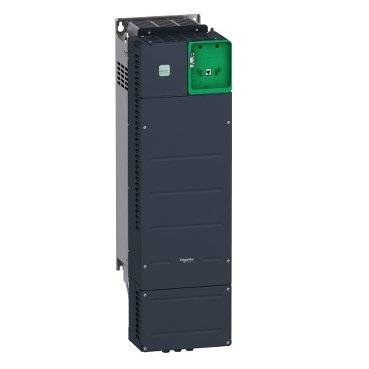
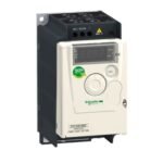
Schneider ATV340D45N4E Altivar | Variable speed drive, Altivar Machine ATV340, 45 kW, 400 V, 3 phases, Ethernet
Schneider ATV340D45N4E Altivar
Description
Schneider ATV340D45N4E Altivar
Energy Efficiency
By optimizing motor speed according to load requirements, the ATV340D45N4E significantly reduces energy consumption, leading to lower operational costs and a smaller carbon footprint. Schneider Electric‘s support tools to analyze and troubleshoot problems. If necessary, contact technical support for further assistance
Enhanced Performance
The drive’s advanced control algorithms ensure smooth and accurate motor operation, minimizing mechanical wear and improving the overall performance of the equipment.
Cost Savings
With reduced energy usage, lower maintenance requirements, and extended equipment life, the ATV340D45N4E offers substantial cost savings over the long term, providing a strong return on investment.
Installation and Setup Guide
Pre-installation Preparations
Before installing the ATV340D45N4E, ensure that the installation environment meets the drive’s requirements, including temperature, humidity, and space considerations.
Choosing the Right Location
Select a well-ventilated area away from direct sunlight, excessive dust, and corrosive substances. Ensure adequate space around the drive for cooling and maintenance.
Electrical Requirements
Verify that the electrical supply matches the drive’s specifications, including voltage, frequency, and current capacity. Use appropriate protective devices and follow local electrical codes.
Installation Process
Once the location and electrical requirements are confirmed, proceed with mounting the drive and making the necessary electrical connections.
Mounting the Drive
Secure the ATV340D45N4E to a stable, vibration-free surface using the mounting holes provided. Ensure proper alignment and secure all fasteners tightly.
Wiring Connections
Connect the input power, motor, and control wiring according to the wiring diagram provided in the manual. Double-check all connections for accuracy and secure them to prevent loosening due to vibration.
Configuration and Programming
After physical installation, configure the drive settings and program the parameters to suit the specific application requirements.
Basic Settings
Set up basic parameters such as motor type, rated voltage, frequency, and acceleration/deceleration times using the drive’s keypad or configuration software.
Advanced Parameters
Adjust advanced settings such as PID control, communication settings, and custom function blocks to optimize the drive’s performance for the specific application.
Maintenance and Troubleshooting
Regular Maintenance Tips
To ensure reliable operation and longevity, perform regular maintenance on the ATV340D45N4E drive.
Inspection
Regularly inspect the drive for signs of wear, damage, or overheating. Check for loose connections, dust buildup, and ensure that the cooling system is functioning properly.
Cleaning
Keep the drive and its surrounding area clean. Use a dry cloth to remove dust from the exterior and compressed air to clean the cooling fins and air intake grilles.
Troubleshooting Common Issues
If the drive encounters operational issues, use the following troubleshooting tips to diagnose and resolve problems.
Error Codes
Refer to the user manual for explanations of error codes displayed on the drive. Follow the recommended corrective actions to resolve the issues.
Diagnostic Tools
Utilize the drive’s built-in diagnostic features and Schneider Electric’s support tools to analyze and troubleshoot problems. If necessary, contact technical support for further assistance.
Case Studies: Real-World Applications
Automotive Manufacturing
In an automotive manufacturing plant, the ATV340D45N4E is used to control assembly line conveyors, providing precise speed control and synchronization to improve production efficiency and product quality.
Food and Beverage Industry
A food processing facility employs the Altivar drive to regulate the speed of mixers and conveyor belts, ensuring consistent product quality and reducing energy consumption.
Water and Wastewater Treatment
The drive is used in water treatment plants to control the speed of pumps and aerators, optimizing flow rates and energy usage while ensuring reliable operation.
Future Trends and Developments
Integration with IoT
The future of industrial automation includes the integration of IoT technologies. The ATV340D45N4E is poised to benefit from this trend, offering enhanced monitoring, predictive maintenance, and data analytics capabilities.
Enhanced Connectivity Options
Schneider Electric is continually developing new connectivity options for the Altivar series, ensuring compatibility with emerging communication standards and protocols to facilitate advanced automation and control.
Predictive Maintenance Features
Future iterations of the Altivar drive are expected to include more sophisticated predictive maintenance features, leveraging machine learning and AI to predict failures and schedule maintenance proactively.
Conclusion
The Schneider ATV340D45N4E Altivar is a powerful and versatile variable speed drive designed to meet the demands of modern industrial applications. Its advanced features, ease of installation, and superior performance make it an ideal choice for enhancing the efficiency and reliability of automation systems. By leveraging the capabilities of this drive, businesses can achieve significant energy savings, improved process control, and reduced operational costs.
Additional information
| brands | Schneider Electric |
|---|
Specifications
| range of product | Altivar Machine ATV340 |
|---|---|
| Product or component typee | Variable speed drive |
| Product specific application | Machine |
| variant | Standard version |
| Mounting mode | Wall mount |
| communication port protocol | Modbus TCP Modbus serial EtherNet/IP |
| Option card | Communication module, PROFINET Communication module, DeviceNet Communication module, CANopen Communication module, EtherCAT |
| Network number of phases | 3 phases |
| Supply frequency | 50...60 Hz +/- 5 % |
| [Us] rated supply voltage | 380...480 V - 15...10 % |
| Nominal output current | 88.0 A |
| Motor power kW | 55 kW for normal duty 45 kW for heavy duty |
| Motor power hp | 75 hp for normal duty 60 hp for heavy duty |
| EMC filter | Class C3 EMC filter integrated |
| IP degree of protection | IP20 |
| Degree of protection | UL type 1 |
| Discrete input number | 8 |
|---|---|
| Discrete input type | PTI safe torque off: 0…30 kHz, 24 V DC (30 V) DI1...DI5 programmable as pulse input, 24 V DC (30 V), impedance: 3.5 kOhm programmable |
| number of preset speeds | 16 preset speeds |
| Discrete output number | 1.0 |
| Discrete output type | Programmable output DQ1, DQ2 30 V DC 100 mA |
| analogue input number | 3 |
| Analogue input type | AI1 software-configurable current: 0...20 mA, impedance: 250 Ohm, resolution 12 bits AI1 software-configurable temperature probe or water level sensor AI1 software-configurable voltage: 0...10 V DC, impedance: 31.5 kOhm, resolution 12 bits AI2 software-configurable voltage: - 10...10 V DC, impedance: 31.5 kOhm, resolution 12 bits |
| analogue output number | 2 |
| Analogue output type | Software-configurable voltage AQ1, AQ2: 0...10 V DC impedance 470 Ohm, resolution 10 bits Software-configurable current AQ1, AQ2: 0...20 mA impedance 500 Ohm, resolution 10 bits |
| Relay output number | 3 |
| Output voltage | <= power supply voltage |
| Relay output type | Relay outputs R1A Relay outputs R1C electrical durability 100000 cycles Relay outputs R2A Relay outputs R2C electrical durability 100000 cycles |
| Maximum switching current | Relay output R1C on resistive load, cos phi = 1: 3 A at 250 V AC Relay output R1C on resistive load, cos phi = 1: 3 A at 30 V DC Relay output R1C on inductive load, cos phi = 0.4 and L/R = 7 ms: 2 A at 250 V AC Relay output R1C on inductive load, cos phi = 0.4 and L/R = 7 ms: 2 A at 30 V DC Relay output R2C on resistive load, cos phi = 1: 5 A at 250 V AC Relay output R2C on resistive load, cos phi = 1: 5 A at 30 V DC Relay output R2C on inductive load, cos phi = 0.4 and L/R = 7 ms: 2 A at 250 V AC Relay output R2C on inductive load, cos phi = 0.4 and L/R = 7 ms: 2 A at 30 V DC |
| Minimum switching current | Relay output R1B: 5 mA at 24 V DC Relay output R2C: 5 mA at 24 V DC |
| Physical interface | 2-wire RS 485 |
| Connector type | 3 RJ45 |
| Method of access | Slave Modbus RTU Slave Modbus TCP |
| Transmission rate | 4.8 kbit/s 9.6 kbit/s 19.2 kbit/s 38.4 kbit/s |
| Transmission frame | RTU |
| Number of addresses | 1…247 |
| Data format | 8 bits, configurable odd, even or no parity |
| Type of polarization | No impedance |
| 4 quadrant operation possible | True |
| Asynchronous motor control profile | Constant torque standard Optimized torque mode Variable torque standard |
| Synchronous motor control profile | Reluctance motor Permanent magnet motor |
| Pollution degree | 2 conforming to IEC 61800-5-1 |
| Maximum output frequency | 0.599 kHz |
| Acceleration and deceleration ramps | S, U or customized Linear adjustable separately from 0.01...9999 s |
| Motor slip compensation | Not available in permanent magnet motor law Can be suppressed Adjustable Automatic whatever the load |
| Switching frequency | 1...8 kHz adjustable 2.5...8 kHz with derating factor |
| Nominal switching frequency | 2.5 kHz |
| Braking to standstill | By DC injection |
| Brake chopper integrated | True |
| Line current | 97.2 A at 380 V (normal duty) 84.2 A at 480 V (normal duty) 81.4 A at 380 V (heavy duty) 71.8 A at 480 V (heavy duty) |
| Line current | 97.2 A at 380 V with internal line choke (normal duty) 84.2 A at 480 V with internal line choke (normal duty) 81.4 A at 380 V with internal line choke (heavy duty) 71.8 A at 480 V with internal line choke (heavy duty) 81.4 A 71.8 A |
| Maximum input current | 97.2 A |
| Maximum output voltage | 480 V |
| Apparent power | 70 kVA at 480 V (normal duty) 59.7 kVA at 480 V (heavy duty) |
| Maximum transient current | 127.2 A during 60 s (normal duty) 132 A during 60 s (heavy duty) 127.2 A during 2 s (normal duty) 132 A during 2 s (heavy duty) |
| Electrical connection | Screw terminal, clamping capacity: 0.75...1.5 mm² for control Screw terminal, clamping capacity: 70...120 mm² for line side Screw terminal, clamping capacity: 70...120 mm² for DC bus Screw terminal, clamping capacity: 70...120 mm² for motor |
| Prospective line Isc | 50 kA |
| Base load current at high overload | 88.0 A |
| Base load current at low overload | 106.0 A |
| Power dissipation in W | Natural convection: 105 W at 380 V, switching frequency 4 kHz (heavy duty) Forced convection: 943 W at 380 V, switching frequency 4 kHz (heavy duty) Natural convection: 115 W at 380 V, switching frequency 4 kHz (normal duty) Forced convection: 917 W at 380 V, switching frequency 4 kHz (normal duty) |
| Electrical connection | Control: screw terminal 0.75...1.5 mm²/AWG 18...AWG 16 Line side: screw terminal 70...120 mm²/AWG 1/0...250 kcmil DC bus: screw terminal 70...120 mm²/AWG 1/0...250 kcmil Motor: screw terminal 70...120 mm²/AWG 1/0...250 kcmil |
| With safety function Safely Limited Speed (SLS) | True |
| With safety function Safe brake management (SBC/SBT) | True |
| With safety function Safe Operating Stop (SOS) | False |
| With safety function Safe Position (SP) | False |
| With safety function Safe programmable logic | False |
| With safety function Safe Speed Monitor (SSM) | False |
| With safety function Safe Stop 1 (SS1) | True |
| With sft fct Safe Stop 2 (SS2) | False |
| With safety function Safe torque off (STO) | True |
| With safety function Safely Limited Position (SLP) | False |
| With safety function Safe Direction (SDI) | False |
| Protection type | Thermal protection: motor Safe torque off: motor Motor phase loss: motor Thermal protection: drive Safe torque off: drive Overheating: drive Overcurrent: drive Output overcurrent between motor phase and earth: drive Output overcurrent between motor phases: drive Short-circuit between motor phase and earth: drive Short-circuit between motor phases: drive Motor phase loss: drive DC Bus overvoltage: drive Line supply overvoltage: drive Line supply undervoltage: drive Input supply loss: drive Exceeding limit speed: drive Break on the control circuit: drive |
| Width | 271.0 mm |
| height | 908.0 mm |
| Depth | 309.0 mm |
| Net weight | 56.4 kg |
| Continuous output current | 106 A at 4 kHz for normal duty 88 A at 4 kHz for heavy duty |
| Operating altitude | <= 4800 m with current derating above 1000m |
|---|---|
| Operating position | Vertical +/- 10 degree |
| product certifications | UL CSA TÜV EAC CTick |
| Marking | CE |
| Standards | IEC 61800-3 IEC 61800-5-1 IEC 60721-3 IEC 61508 IEC 13849-1 UL 618000-5-1 UL 508C IEC 61000-3-12 |
| Maximum THDI | <48 % full load conforming to IEC 61000-3-12 <48 % 80 % load conforming to IEC 61000-3-12 |
| Assembly style | With heat sink |
| Electromagnetic compatibility | Electrostatic discharge immunity test level 3 conforming to IEC 61000-4-2 Radiated radio-frequency electromagnetic field immunity test level 3 conforming to IEC 61000-4-3 Electrical fast transient/burst immunity test level 4 conforming to IEC 61000-4-4 1.2/50 µs - 8/20 µs surge immunity test level 3 conforming to IEC 61000-4-5 Conducted radio-frequency immunity test level 3 conforming to IEC 61000-4-6 |
| Environmental class (during operation) | Class 3C3 according to IEC 60721-3-3 Class 3S3 according to IEC 60721-3-3 |
| Maximum acceleration under shock impact (during operation) | 150 m/s² at 11 ms |
| Maximum acceleration under vibrational stress (during operation) | 10 m/s² at 13...200 Hz |
| Maximum deflection under vibratory load (during operation) | 1.5 mm at 2...13 Hz |
| Permitted relative humidity (during operation) | Class 3K5 according to EN 60721-3 |
| Volume of cooling air | 295.0 m3/h |
| Type of cooling | Forced convection |
| Overvoltage category | Class III |
| Regulation loop | Adjustable PID regulator |
| Noise level | 62.4 dB |
| Pollution degree | 2 |
| Ambient air transport temperature | -40…70 °C |
| Ambient air temperature for operation | -15…50 °C without derating (vertical position) 50…60 °C with derating factor (vertical position) |
| Ambient air temperature for storage | -40…70 °C |
| Isolation | Between power and control terminals |
| Unit Type of Package 1 | PCE |
|---|---|
| Number of Units in Package 1 | 1 |
| Package 1 Height | 60 cm |
| Package 1 Width | 43 cm |
| Package 1 Length | 111 cm |
| Package 1 Weight | 66 kg |
Reviews
There are no reviews yet.