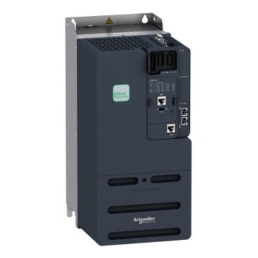
Schneider ATV340D22N4E Altivar | Variable speed drive, Altivar Machine ATV340, 22 kW, 400 V, 3 phases, Ethernet
Schneider ATV340D22N4E Altivar
Description
Schneider ATV340D22N4E Altivar
Introduction
In the realm of industrial automation, the Schneider ATV340D22N4E Altivar stands as a pinnacle of innovation and efficiency. This article delves into the intricacies of this cutting-edge variable frequency drive (VFD), exploring its features, applications, and benefits in modern industrial setups.
Understanding Variable Frequency Drives (VFDs)
What are VFDs?
Variable frequency drives, commonly known as VFDs, are devices used to control the speed and torque of electric motors by varying the frequency and voltage supplied to the motor.
The Functionality of VFDs
VFDs regulate the speed of an electric motor by adjusting the frequency of the electrical power supplied to it. This allows for precise control over motor speed, resulting in energy savings and improved performance.
Advantages of Using VFDs
Using VFDs offers several advantages, including energy savings, reduced wear and tear on equipment, and improved process control in industrial applications.
Introducing Schneider ATV340D22N4E Altivar
Overview
The Schneider ATV340D22N4E Altivar is a state-of-the-art variable frequency drive designed for demanding industrial environments. It offers superior performance, reliability, and flexibility.
Key Features of Schneider ATV340D22N4E Altivar
- High-performance motor control
- Advanced communication options
- Built-in safety features
- Energy-efficient design
- Easy installation and configuration
Technical Specifications
- Model: ATV340D22N4E
- Voltage: 380-480V
- Power Rating: 22 kW
- Frequency Range: 0.1 to 599 Hz
- Control: Sensorless flux vector control
Applications of Schneider ATV340D22N4E Altivar
The Schneider ATV340D22N4E Altivar is suitable for a wide range of applications, including pumps, fans, conveyors, and compressors, across various industries such as manufacturing, water treatment, and HVAC.
Benefits of Utilizing Schneider ATV340D22N4E Altivar
Enhanced Energy Efficiency
The Schneider ATV340D22N4E Altivar helps optimize energy usage by precisely matching motor speed to the required load, resulting in significant energy savings.
Precise Motor Control
With its advanced motor control algorithms, the Altivar ensures smooth operation and precise speed control, enhancing productivity and product quality.
Reduced Maintenance Costs
The robust design and built-in diagnostics of the Altivar minimize downtime and maintenance costs, leading to improved reliability and operational efficiency.
Installation and Setup
Installation Process
The Altivar features a user-friendly design for easy installation, with clear instructions provided in the product manual.
Configuration Steps
Configuring the Altivar is straightforward, thanks to its intuitive interface and comprehensive parameter settings.
Optimizing Performance
Fine-tuning the Altivar for optimal performance involves adjusting parameters such as motor speed, acceleration, and deceleration rates to match specific application requirements.
Safety Features
Built-in Protection Mechanisms
The Altivar is equipped with built-in protection features such as thermal overload protection, short-circuit protection, and motor phase loss detection to ensure safe and reliable operation.
Safety Compliance
It complies with international safety standards, providing peace of mind to users regarding equipment and personnel safety.
Maintenance and Troubleshooting
Routine Maintenance
Regular maintenance tasks include inspecting the drive for signs of wear, checking electrical connections, and keeping the enclosure clean and free from debris.
Common Issues and Troubleshooting
Common issues such as motor overheating or abnormal operation can be diagnosed and resolved using the Altivar’s built-in diagnostic tools and troubleshooting guides.
Comparison with Alternatives
Schneider ATV340D22N4E Altivar vs. Traditional Motor Starters
Compared to traditional motor starters, the Altivar offers superior motor control, energy efficiency, and flexibility, making it the preferred choice for modern industrial applications.
Schneider ATV340D22N4E Altivar vs. Other VFD Models
The Altivar distinguishes itself from other VFD models with its advanced features, robust construction, and seamless integration capabilities, catering to the diverse needs of industrial users.
Additional information
| brands | Schneider Electric |
|---|
Specifications
| Range of product | Altivar Machine ATV340 |
|---|---|
| Product or component type | Variable speed drive |
| Product specific application | Machine |
| variant | Standard version |
| Mounting mode | Cabinet mount |
| communication port protocol | Modbus TCP EtherNet/IP Modbus serial |
| Network number of phases | 3 phases |
| Supply frequency | 50...60 Hz +/- 5 % |
| [Us] rated supply voltage | 380...480 V - 15...10 % |
| Nominal output current | 46.0 A |
| Motor power kW | 30 kW for normal duty 22 kW for heavy duty |
| Motor power hp | 40 hp for normal duty 30 hp for heavy duty |
| EMC filter | Class C3 EMC filter integrated |
| IP degree of protection | IP20 |
| Discrete input number | 5 |
|---|---|
| Discrete input type | PTI programmable as pulse input: 0…30 kHz, 24 V DC (30 V) DI1...DI5 safe torque off, 24 V DC (30 V), impedance: 3.5 kOhm programmable |
| number of preset speeds | 16 preset speeds |
| Discrete output number | 2.0 |
| Discrete output type | Programmable output DQ1, DQ2 30 V DC 100 mA |
| analogue input number | 2 |
| Analogue input type | AI1 software-configurable current: 0...20 mA, impedance: 250 Ohm, resolution 12 bits AI1 software-configurable temperature probe or water level sensor AI1 software-configurable voltage: 0...10 V DC, impedance: 31.5 kOhm, resolution 12 bits AI2 software-configurable voltage: - 10...10 V DC, impedance: 31.5 kOhm, resolution 12 bits |
| analogue output number | 2 |
| Analogue output type | Software-configurable voltage AQ1: 0...10 V DC impedance 470 Ohm, resolution 10 bits Software-configurable current AQ1: 0...20 mA impedance 500 Ohm, resolution 10 bits |
| Relay output number | 2 |
| Output voltage | <= power supply voltage |
| Relay output type | Relay outputs R1A Relay outputs R1C electrical durability 100000 cycles Relay outputs R2A Relay outputs R2C electrical durability 100000 cycles |
| Maximum switching current | Relay output R1C on resistive load, cos phi = 1: 3 A at 250 V AC Relay output R1C on resistive load, cos phi = 1: 3 A at 30 V DC Relay output R1C on inductive load, cos phi = 0.4 and L/R = 7 ms: 2 A at 250 V AC Relay output R1C on inductive load, cos phi = 0.4 and L/R = 7 ms: 2 A at 30 V DC Relay output R2C on resistive load, cos phi = 1: 5 A at 250 V AC Relay output R2C on resistive load, cos phi = 1: 5 A at 30 V DC Relay output R2C on inductive load, cos phi = 0.4 and L/R = 7 ms: 2 A at 250 V AC Relay output R2C on inductive load, cos phi = 0.4 and L/R = 7 ms: 2 A at 30 V DC |
| Minimum switching current | Relay output R1B: 5 mA at 24 V DC Relay output R2C: 5 mA at 24 V DC |
| Physical interface | 2-wire RS 485 |
| Connector type | 3 RJ45 |
| Method of access | Slave Modbus RTU Slave Modbus TCP |
| Transmission rate | 4.8 kbit/s 9.6 kbit/s 19.2 kbit/s 38.4 kbit/s |
| Transmission frame | RTU |
| Number of addresses | 1…247 |
| Data format | 8 bits, configurable odd, even or no parity |
| Type of polarization | No impedance |
| 4 quadrant operation possible | True |
| Asynchronous motor control profile | Optimized torque mode Constant torque standard Variable torque standard |
| Synchronous motor control profile | Permanent magnet motor Reluctance motor |
| Pollution degree | 2 conforming to IEC 61800-5-1 |
| Maximum output frequency | 0.599 kHz |
| Acceleration and deceleration ramps | S, U or customized Linear adjustable separately from 0.01...9999 s |
| Motor slip compensation | Automatic whatever the load Can be suppressed Adjustable Not available in permanent magnet motor law |
| Switching frequency | 2...16 kHz adjustable 6...16 kHz with derating factor |
| Nominal switching frequency | 4 kHz |
| Braking to standstill | By DC injection |
| Brake chopper integrated | True |
| Line current | 60.1 A at 380 V (normal duty) 48.6 A at 480 V (normal duty) 63.5 A at 380 V (heavy duty) 50.6 A at 480 V (heavy duty) |
| Line current | 63.5 A at 380 V without line choke (heavy duty) 50.5 A at 480 V without line choke (heavy duty) 67.9 A at 480 V with external line choke (normal duty) 54.4 A at 380 V with external line choke (heavy duty) 64.1 A at 480 V with external line choke (heavy duty) 50.8 A at 380 V with external line choke (normal duty) |
| Maximum input current | 63.5 A |
| Maximum output voltage | 480 V |
| Apparent power | 45.1 kVA at 480 V (normal duty) 42.1 kVA at 480 V (heavy duty) |
| Maximum transient current | 68.2 A during 60 s (normal duty) 69 A during 60 s (heavy duty) 83.7 A during 2 s (normal duty) 83 A during 2 s (heavy duty) |
| Electrical connection | Screw terminal, clamping capacity: 0.2...2.5 mm² for control Screw terminal, clamping capacity: 6...25 mm² for motor Screw terminal, clamping capacity: 10...25 mm² for line side Screw terminal, clamping capacity: 10...25 mm² for DC bus |
| Prospective line Isc | 22 kA |
| Base load current at high overload | 46.0 A |
| Base load current at low overload | 62.0 A |
| Power dissipation in W | Natural convection: 28 W at 380 V, switching frequency 4 kHz (heavy duty) Forced convection: 486 W at 380 V, switching frequency 4 kHz (heavy duty) Natural convection: 39 W at 380 V, switching frequency 4 kHz (normal duty) Forced convection: 631 W at 380 V, switching frequency 4 kHz (normal duty) |
| Electrical connection | Control: screw terminal 0.2...2.5 mm²/AWG 24...AWG 12 Motor: screw terminal 6...25 mm²/AWG 8...AWG 3 Line side: screw terminal 10...25 mm²/AWG 6...AWG 3 DC bus: screw terminal 10...25 mm²/AWG 6...AWG 3 |
| With safety function Safely Limited Speed (SLS) | True |
| With safety function Safe brake management (SBC/SBT) | True |
| With safety function Safe Operating Stop (SOS) | False |
| With safety function Safe Position (SP) | False |
| With safety function Safe programmable logic | False |
| With safety function Safe Speed Monitor (SSM) | False |
| With safety function Safe Stop 1 (SS1) | True |
| With sft fct Safe Stop 2 (SS2) | False |
| With safety function Safe torque off (STO) | True |
| With safety function Safely Limited Position (SLP) | False |
| With safety function Safe Direction (SDI) | False |
| Protection type | Thermal protection: motor Safe torque off: motor Motor phase loss: motor Thermal protection: drive Safe torque off: drive Overheating: drive Overcurrent: drive Output overcurrent between motor phase and earth: drive Output overcurrent between motor phases: drive Short-circuit between motor phase and earth: drive Short-circuit between motor phases: drive Motor phase loss: drive DC Bus overvoltage: drive Line supply overvoltage: drive Line supply undervoltage: drive Input supply loss: drive Exceeding limit speed: drive Break on the control circuit: drive |
| Width | 180.0 mm |
| height | 385.0 mm |
| Depth | 249.0 mm |
| Net weight | 10.2 kg |
| Continuous output current | 62 A at 4 kHz for normal duty 46 A at 4 kHz for heavy duty |
| Operating altitude | <= 3000 m with current derating above 1000m |
|---|---|
| Operating position | Vertical +/- 10 degree |
| product certifications | UL CSA TÜV EAC CTick |
| Marking | CE |
| Standards | IEC 61800-3 IEC 61800-5-1 IEC 60721-3 IEC 61508 IEC 13849-1 UL 618000-5-1 UL 508C |
| Assembly style | With heat sink |
| Electromagnetic compatibility | Electrostatic discharge immunity test level 3 conforming to IEC 61000-4-2 Radiated radio-frequency electromagnetic field immunity test level 3 conforming to IEC 61000-4-3 Electrical fast transient/burst immunity test level 4 conforming to IEC 61000-4-4 1.2/50 µs - 8/20 µs surge immunity test level 3 conforming to IEC 61000-4-5 Conducted radio-frequency immunity test level 3 conforming to IEC 61000-4-6 |
| Environmental class (during operation) | Class 3C3 according to IEC 60721-3-3 Class 3S3 according to IEC 60721-3-3 |
| Maximum acceleration under shock impact (during operation) | 70 m/s² at 22 ms |
| Maximum acceleration under vibrational stress (during operation) | 5 m/s² at 9...200 Hz |
| Maximum deflection under vibratory load (during operation) | 1.5 mm at 2...9 Hz |
| Permitted relative humidity (during operation) | Class 3K5 according to EN 60721-3 |
| Volume of cooling air | 128.0 m3/h |
| Type of cooling | Forced convection |
| Overvoltage category | Class III |
| Regulation loop | Adjustable PID regulator |
| Noise level | 56.7 dB |
| Pollution degree | 2 |
| Ambient air transport temperature | -40…70 °C |
| Ambient air temperature for operation | -15…50 °C without derating (vertical position) 50…60 °C with derating factor (vertical position) |
| Ambient air temperature for storage | -40…70 °C |
| Isolation | Between power and control terminals |
| Unit Type of Package 1 | PCE |
|---|---|
| Number of Units in Package 1 | 1 |
| Package 1 Height | 29.800 cm |
| Package 1 Width | 54.800 cm |
| Package 1 Length | 33.700 cm |
| Package 1 Weight | 11.890 kg |
| Unit Type of Package 2 | P06 |
| Number of Units in Package 2 | 2 |
| Package 2 Height | 75.000 cm |
| Package 2 Width | 60.000 cm |
| Package 2 Length | 80.000 cm |
| Package 2 Weight | 36.780 kg |
Reviews
There are no reviews yet.