
No products in the cart.
-45%On Sale

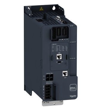
Schneider ATV340U75N4 | Variable speed drive, Altivar Machine ATV340, 7.5 kW, 400 V, 3 phases,
Schneider ATV340U75N4 | Variable speed drive, Altivar Machine ATV340, 7.5 kW, 400 V, 3 phases,
Original price was: EGP 102,641.95.EGP 56,453.10Current price is: EGP 56,453.10.
Description
Schneider ATV340U75N4: The Ultimate Guide
Introduction
When it comes to efficient motor control in industrial applications, the Schneider ATV340U75N4 stands out as a reliable and advanced solution. Understanding its features, benefits, and applications can significantly enhance your operational efficiency. This article aims to provide an in-depth look at the Schneider ATV340U75N4, from its key specifications to practical tips for installation and use.
Understanding the Schneider ATV340U75N4
What is the Schneider ATV340U75N4?
The Schneider ATV340U75N4 is a variable frequency drive (VFD) designed to optimize the performance of various industrial applications. It provides precise motor control, enhancing the performance and efficiency of your machinery.
Key Features and Specifications
- Power Rating: 7.5 kW (10 HP)
- Input Voltage: 380-480V, 3-phase
- Output Frequency: 0.5 to 400 Hz
- Control Type: Vector control with sensorless vector capability
- Protection: IP20 enclosure, overcurrent, overvoltage, and thermal protection
Benefits of Using the Schneider ATV340U75N4
- Energy Efficiency: Reduces energy consumption by optimizing motor speed.
- Ease of Use: User-friendly interface and simple configuration.
- Reliability: Robust design ensures long-term performance.
- Versatility: Suitable for a wide range of applications.
Applications of the Schneider ATV340U75N4
Common Industries and Use Cases
The Schneider ATV340U75N4 is commonly used in:
- Manufacturing: Enhancing production line efficiency.
- Material Handling: Controlling conveyors and cranes for better operation.
- Pumps and Fans: Managing speed for improved process control.
- HVAC Systems: Ensuring optimal performance and energy efficiency.
Real-World Examples of Implementation
- Automotive Industry: Improving precision in assembly lines.
- Food and Beverage: Enhancing the efficiency of processing equipment.
- Chemical Plants: Ensuring consistent operation of pumps and mixers.
Advantages in Specific Applications
- Precision Control: Achieving desired performance in various processes.
- Cost Savings: Lowering energy bills and maintenance costs.
- Improved Durability: Extending the lifespan of your equipment.
Installation and Setup
Pre-installation Considerations
- Verify Electrical Specifications: Ensure compatibility with your power supply.
- Check Environmental Conditions: Install in a clean, dry, and well-ventilated area.
Step-by-Step Installation Guide
- Mount the VFD: Securely mount the Schneider ATV340U75N4 on a stable surface.
- Connect the Power Supply: Follow the wiring diagram to connect to the power source.
- Wire the Motor: Connect the motor terminals to the VFD outputs.
- Configure the Settings: Use the interface to set initial parameters.
Initial Setup and Configuration
- Parameter Setting: Configure parameters like motor voltage, current, and frequency.
- Test Run: Perform a test run to ensure proper operation.
Operating the Schneider ATV340U75N4
Basic Operation Principles
- Start/Stop Control: Use the interface to start and stop the motor.
- Speed Adjustment: Adjust motor speed using the control panel.
User Interface and Controls
- LCD Display: Provides real-time data on motor performance.
- Keypad: Allows for easy parameter adjustments.
Tips for Efficient Operation
- Regular Monitoring: Keep an eye on performance metrics.
- Optimal Settings: Fine-tune settings for your specific application.
Maintenance and Troubleshooting
Regular Maintenance Practices
- Routine Inspections: Check for dust buildup and clean regularly.
- Firmware Updates: Ensure the VFD firmware is up-to-date.
Common Issues and Their Solutions
- Overheating: Ensure proper ventilation and reduce load if necessary.
- Unexpected Shutdowns: Check for electrical faults or parameter errors.
When to Seek Professional Help
- Complex Issues: If troubleshooting doesn’t resolve the problem, consult a professional.
- Major Repairs: For significant damage, professional repair is recommended.
Advanced Features and Customization
Overview of Advanced Functionalities
- Programmable Logic: Customize operations with built-in programming options.
- Remote Monitoring: Integrate with supervisory systems for remote monitoring.
Customization Options
- User-defined Parameters: Tailor settings to your specific needs.
- Interface Options: Choose between different user interfaces for control.
Integrating with Other Systems
- Communication Protocols: Supports Modbus and other protocols for seamless integration.
- Automation Systems: Compatible with various automation and control systems.
Energy Efficiency and Cost Savings
How the ATV340U75N4 Enhances Energy Efficiency
- Variable Speed Control: Matches motor speed to the actual load requirement.
- Reduced Power Consumption: Lowers energy usage during low-demand periods.
Cost-saving Benefits
- Lower Utility Bills: Reduced energy consumption translates to savings.
- Extended Equipment Life: Proper motor control reduces wear and tear.
Environmental Impact
- Reduced Carbon Footprint: Lower energy consumption helps in reducing greenhouse gas emissions.
- Sustainable Operations: Supports your sustainability goals.
Additional information
| brands | Schneider Electric |
|---|
Specifications
| Range of product | Altivar Machine ATV340 |
|---|---|
| product or component type | Variable speed drive |
| Product specific application | Machine |
| variant | Standard version |
| mounting mode | Cabinet mount |
| Communication port protocol | Modbus serial |
| Option card | Communication module, Profibus DP V1 Communication module, PROFINET Communication module, DeviceNet Communication module, CANopen Communication module, EtherCAT |
| Network number of phases | 3 phases |
| Supply frequency | 50...60 Hz +/- 5 % |
| [Us] rated supply voltage | 380...480 V - 15...10 % |
| Nominal output current | 16.5 A |
| Motor power kW | 11 kW for normal duty 7.5 kW for heavy duty |
| Motor power hp | 15 hp for normal duty 10 hp for heavy duty |
| EMC filter | Class C3 EMC filter integrated |
| IP degree of protection | IP20 |
| Discrete input number | 5 |
|---|---|
| Discrete input type | PTI programmable as pulse input: 0…30 kHz, 24 V DC (30 V) DI1...DI5 safe torque off, 24 V DC (30 V), impedance: 3.5 kOhm programmable |
| number of preset speeds | 16 preset speeds |
| Discrete output number | 2.0 |
| Discrete output type | Programmable output DQ1, DQ2 30 V DC 100 mA |
| Analogue input number | 2 |
| Analogue input type | AI1 software-configurable current: 0...20 mA, impedance: 250 Ohm, resolution 12 bits AI1 software-configurable temperature probe or water level sensor AI1 software-configurable voltage: 0...10 V DC, impedance: 31.5 kOhm, resolution 12 bits AI2 software-configurable voltage: - 10...10 V DC, impedance: 31.5 kOhm, resolution 12 bits |
| Analogue output number | 1 |
| Analogue output type | Software-configurable voltage AQ1: 0...10 V DC impedance 470 Ohm, resolution 10 bits Software-configurable current AQ1: 0...20 mA impedance 500 Ohm, resolution 10 bits |
| Relay output number | 2 |
| Output voltage | <= power supply voltage |
| Relay output type | Relay outputs R1A Relay outputs R1C electrical durability 100000 cycles Relay outputs R2A Relay outputs R2C electrical durability 100000 cycles |
| Maximum switching current | Relay output R1C on resistive load, cos phi = 1: 3 A at 250 V AC Relay output R1C on resistive load, cos phi = 1: 3 A at 30 V DC Relay output R1C on inductive load, cos phi = 0.4 and L/R = 7 ms: 2 A at 250 V AC Relay output R1C on inductive load, cos phi = 0.4 and L/R = 7 ms: 2 A at 30 V DC Relay output R2C on resistive load, cos phi = 1: 5 A at 250 V AC Relay output R2C on resistive load, cos phi = 1: 5 A at 30 V DC Relay output R2C on inductive load, cos phi = 0.4 and L/R = 7 ms: 2 A at 250 V AC Relay output R2C on inductive load, cos phi = 0.4 and L/R = 7 ms: 2 A at 30 V DC |
| Minimum switching current | Relay output R1B: 5 mA at 24 V DC Relay output R2C: 5 mA at 24 V DC |
| Physical interface | 2-wire RS 485 |
| Connector type | 1 RJ45 |
| Method of access | Slave Modbus RTU |
| Transmission rate | 4.8 kbit/s 9.6 kbit/s 19.2 kbit/s 38.4 kbit/s |
| Transmission frame | RTU |
| Number of addresses | 1…247 |
| Data format | 8 bits, configurable odd, even or no parity |
| Type of polarization | No impedance |
| 4 quadrant operation possible | True |
| Asynchronous motor control profile | Variable torque standard Constant torque standard Optimized torque mode |
| Synchronous motor control profile | Permanent magnet motor Reluctance motor |
| Pollution degree | 2 conforming to IEC 61800-5-1 |
| Maximum output frequency | 0.599 kHz |
| Acceleration and deceleration ramps | Linear adjustable separately from 0.01...9999 s S, U or customized |
| Motor slip compensation | Automatic whatever the load Can be suppressed Adjustable Not available in permanent magnet motor law |
| Switching frequency | 2...16 kHz adjustable 4...16 kHz with derating factor |
| Nominal switching frequency | 4 kHz |
| Braking to standstill | By DC injection |
| Brake chopper integrated | True |
| Line current | 22.0 A at 380 V (normal duty) 17.7 A at 480 V (normal duty) 25.6 A at 380 V (heavy duty) 20.4 A at 480 V (heavy duty) |
| Line current | 25.6 A at 380 V without line choke (heavy duty) 20.4 A at 480 V without line choke (heavy duty) 22 A at 380 V with external line choke (normal duty) 17.7 A at 480 V with external line choke (normal duty) 14.6 A at 380 V with external line choke (heavy duty) 12.1 A at 480 V with external line choke (heavy duty) |
| Maximum input current | 25.6 A |
| Maximum output voltage | 480 V |
| Apparent power | 17 kVA at 480 V (normal duty) 17 kVA at 480 V (heavy duty) |
| Maximum transient current | 26.4 A during 60 s (normal duty) 24.8 A during 60 s (heavy duty) 32.4 A during 2 s (normal duty) 29.7 A during 2 s (heavy duty) |
| Electrical connection | Screw terminal, clamping capacity: 4...6 mm² for DC bus Screw terminal, clamping capacity: 0.2...2.5 mm² for control Screw terminal, clamping capacity: 1.5...6 mm² for motor Screw terminal, clamping capacity: 2.5...6 mm² for line side |
| Prospective line Isc | 22 kA |
| Base load current at high overload | 16.5 A |
| Base load current at low overload | 24.0 A |
| Power dissipation in W | Natural convection: 180 W at 380 V, switching frequency 4 kHz (heavy duty) Forced convection: 180 W at 380 V, switching frequency 4 kHz (heavy duty) Natural convection: 249 W at 380 V, switching frequency 4 kHz (normal duty) Forced convection: 249 W at 380 V, switching frequency 4 kHz (normal duty) |
| Electrical connection | DC bus: screw terminal 4...6 mm²/AWG 12...AWG 10 Control: screw terminal 0.2...2.5 mm²/AWG 24...AWG 12 Motor: screw terminal 1.5...6 mm²/AWG 14...AWG 10 Line side: screw terminal 2.5...6 mm²/AWG 12...AWG 10 |
| With safety function Safely Limited Speed (SLS) | True |
| With safety function Safe brake management (SBC/SBT) | True |
| With safety function Safe Operating Stop (SOS) | False |
| With safety function Safe Position (SP) | False |
| With safety function Safe programmable logic | False |
| With safety function Safe Speed Monitor (SSM) | False |
| With safety function Safe Stop 1 (SS1) | True |
| With sft fct Safe Stop 2 (SS2) | False |
| With safety function Safe torque off (STO) | True |
| With safety function Safely Limited Position (SLP) | False |
| With safety function Safe Direction (SDI) | False |
| Protection type | Thermal protection: motor Safe torque off: motor Motor phase loss: motor Thermal protection: drive Safe torque off: drive Overheating: drive Overcurrent: drive Output overcurrent between motor phase and earth: drive Output overcurrent between motor phases: drive Short-circuit between motor phase and earth: drive Short-circuit between motor phases: drive Motor phase loss: drive DC Bus overvoltage: drive Line supply overvoltage: drive Line supply undervoltage: drive Input supply loss: drive Exceeding limit speed: drive Break on the control circuit: drive |
| Width | 110.0 mm |
| Height | 270.0 mm |
| Depth | 234.0 mm |
| net weight | 3.0 kg |
| Continuous output current | 24 A at 4 kHz for normal duty 16.5 A at 4 kHz for heavy duty |
| Operating altitude | <= 3000 m with current derating above 1000m |
|---|---|
| Operating position | Vertical +/- 10 degree |
| Product certifications | UL CSA TÜV EAC CTick |
| marking | CE |
| Standards | IEC 61800-3 IEC 61800-5-1 IEC 60721-3 IEC 61508 IEC 13849-1 UL 618000-5-1 UL 508C |
| Assembly style | With heat sink |
| Electromagnetic compatibility | Electrostatic discharge immunity test level 3 conforming to IEC 61000-4-2 Radiated radio-frequency electromagnetic field immunity test level 3 conforming to IEC 61000-4-3 Electrical fast transient/burst immunity test level 4 conforming to IEC 61000-4-4 1.2/50 µs - 8/20 µs surge immunity test level 3 conforming to IEC 61000-4-5 Conducted radio-frequency immunity test level 3 conforming to IEC 61000-4-6 |
| Environmental class (during operation) | Class 3C3 according to IEC 60721-3-3 Class 3S3 according to IEC 60721-3-3 |
| Maximum acceleration under shock impact (during operation) | 70 m/s² at 22 ms |
| Maximum acceleration under vibrational stress (during operation) | 5 m/s² at 9...200 Hz |
| Maximum deflection under vibratory load (during operation) | 1.5 mm at 2...9 Hz |
| Permitted relative humidity (during operation) | Class 3K5 according to EN 60721-3 |
| Volume of cooling air | 76.0 m3/h |
| Type of cooling | Forced convection |
| Overvoltage category | Class III |
| Regulation loop | Adjustable PID regulator |
| Noise level | 46.5 dB |
| Pollution degree | 2 |
| Ambient air transport temperature | -40…70 °C |
| Ambient air temperature for operation | -15…50 °C without derating (vertical position) 50…60 °C with derating factor (vertical position) |
| Ambient air temperature for storage | -40…70 °C |
| Isolation | Between power and control terminals |
| Unit Type of Package 1 | PCE |
|---|---|
| Number of Units in Package 1 | 1 |
| Package 1 Height | 13.200 cm |
| Package 1 Width | 37.000 cm |
| Package 1 Length | 32.000 cm |
| Package 1 Weight | 3.770 kg |
| Unit Type of Package 2 | P06 |
| Number of Units in Package 2 | 10 |
| Package 2 Height | 75.000 cm |
| Package 2 Width | 60.000 cm |
| Package 2 Length | 80.000 cm |
| Package 2 Weight | 50.700 kg |


Reviews
There are no reviews yet.