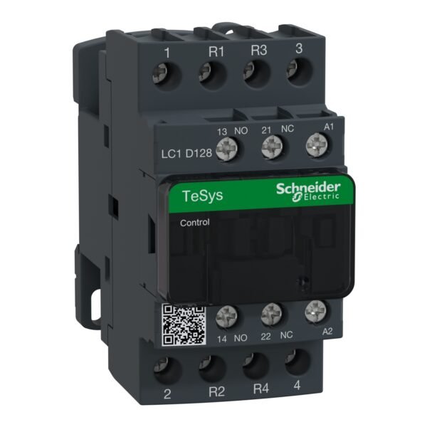
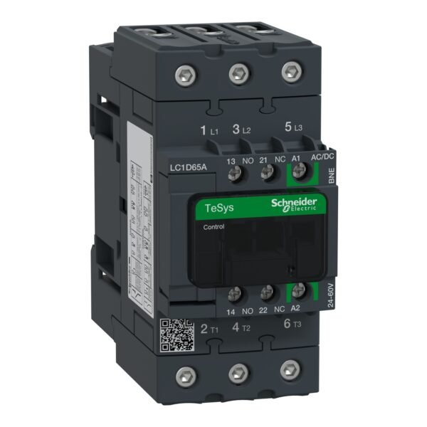
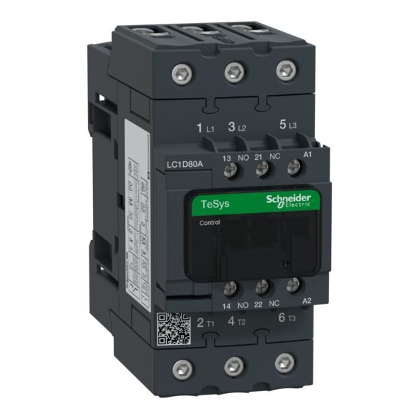
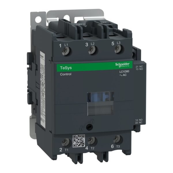
Schneider LC1D128F7 Contactor | TeSys D contactor – 4P(2 NO + 2 NC) – AC-1 – <= 440 V 25 A – 110 V AC coil
Schneider LC1D128F7 Contactor
Description
Schneider LC1D128F7 Contactor: Streamlining Electrical Operations
it is a critical component in various electrical systems, renowned for its reliability and efficiency. In this article, we’ll delve into the intricacies of this contactor, understanding its functionality, features, applications, installation process, and maintenance tips.
Understanding Contactor Basics
What is a contactor? A contactor is an electromechanical switch used to control an electrical circuit. It consists of a coil that when energized, creates a magnetic field, attracting contacts to make or break a connection.
How does a contactor work? When the coil is energized, the magnetic field pulls the contacts together, completing the circuit. Conversely, when the coil is de-energized, the contacts separate, interrupting the circuit.
Features of Schneider LC1D128F7 Contactor
it boasts several features that make it a preferred choice for various applications.
- Voltage rating: Suitable for a wide range of voltage requirements.
- Current rating: Capable of handling high currents, ensuring reliable operation.
- Coil voltage: Available in different coil voltage options for compatibility.
- Contact material: Utilizes high-quality contact material for longevity and efficiency.
Applications of Schneider LC1D128F7 Contactor
This contactor finds its application across diverse industries and sectors, including:
- Industrial machinery: Used in motor control applications for manufacturing processes.
- HVAC systems: Facilitates the control of heating, ventilation, and air conditioning systems.
- Elevators: Ensures safe and efficient operation of elevator systems.
Installation and Wiring
Proper installation and wiring are crucial for the optimal performance of the Schneider LC1D128F7 Contactor. Refer to the manufacturer’s instructions for:
- Mounting instructions: Ensure secure mounting to prevent vibrations and damage.
- Wiring diagram: Follow the provided wiring diagram for correct connection of terminals.
Benefits of Using Schneider LC1D128F7 Contactor
- Reliability: With robust construction, the contactor offers dependable performance in demanding environments.
- Efficiency: Minimizes energy loss and heat generation, contributing to overall system efficiency.
- Safety: Incorporates features to prevent arcing and ensure safe operation for both equipment and personnel.
Maintenance Tips
To prolong the lifespan and ensure optimal performance of the contactor, adhere to the following maintenance practices:
- Regular inspection: Check for signs of wear, corrosion, or damage and replace components as needed.
- Cleaning procedures: Keep the contact surfaces clean and free from debris to maintain proper contact.
Troubleshooting Common Issues
Despite its reliability, the Schneider LC1D128F7 Contactor may encounter issues such as:
- Overheating: Check for inadequate ventilation or excessive load.
- Failure to operate: Inspect the coil and control circuit for faults.
- Coil problems: Verify coil continuity and voltage supply.
Comparing Schneider LC1D128F7 Contactor with Competitors
When selecting a contactor, consider factors like price, performance, and durability. Compare the Schneider LC1D128F7 Contactor with competitors to make an informed decision.
Customer Reviews and Testimonials
Gather insights from customer reviews and testimonials to understand real-world experiences with the Schneider LC1D128F7 Contactor.
Conclusion
The Schneider LC1D128F7 Contactor stands as a reliable and efficient solution for diverse electrical control applications. With its robust construction, advanced features, and proven performance, it continues to be a preferred choice for professionals across industries.
Additional information
| brands | Schneider Electric |
|---|
Specifications
| Range of product | TeSys Deca |
|---|---|
| Product or component type | Contactor |
| Device short name | LC1D |
| Contactor application | Resistive load |
| Utilisation category | AC-1 AC-3 AC-3e AC-4 |
| Poles description | 4P |
| [Ue] rated operational voltage | Power circuit: <= 690 V AC 25...400 Hz Power circuit: <= 300 V DC |
| [Ie] rated operational current | 25 A (at <60 °C) at <= 440 V AC AC-1 for power circuit |
| [Uc] control circuit voltage | 110 V AC 50/60 Hz |
| Compatibility code | LC1D |
|---|---|
| Pole contact composition | 2 NO + 2 NC |
| Protective cover | With |
| [Ith] conventional free air thermal current | 25 A (at 60 °C) for power circuit 10 A (at 60 °C) for signalling circuit |
| Irms rated making capacity | 250 A at 440 V for power circuit conforming to IEC 60947 140 A AC for signalling circuit conforming to IEC 60947-5-1 250 A DC for signalling circuit conforming to IEC 60947-5-1 |
| Rated breaking capacity | 250 A at 440 V for power circuit conforming to IEC 60947 |
| [Icw] rated short-time withstand current | 105 A 40 °C - 10 s for power circuit 210 A 40 °C - 1 s for power circuit 30 A 40 °C - 10 min for power circuit 61 A 40 °C - 1 min for power circuit 100 A - 1 s for signalling circuit 120 A - 500 ms for signalling circuit 140 A - 100 ms for signalling circuit |
| Associated fuse rating | 10 A gG for signalling circuit conforming to IEC 60947-5-1 40 A gG at <= 690 V coordination type 1 for power circuit 25 A gG at <= 690 V coordination type 2 for power circuit |
| Average impedance | 2.5 mOhm - Ith 25 A 50 Hz for power circuit |
| Power dissipation per pole | 1.56 W AC-1 |
| [Ui] rated insulation voltage | Power circuit: 690 V conforming to IEC 60947-4-1 Power circuit: 600 V CSA certified Power circuit: 600 V UL certified Signalling circuit: 690 V conforming to IEC 60947-1 Signalling circuit: 600 V CSA certified Signalling circuit: 600 V UL certified |
| Overvoltage category | III |
| Pollution degree | 3 |
| [Uimp] rated impulse withstand voltage | 6 kV conforming to IEC 60947 |
| Safety reliability level | B10d = 1369863 cycles contactor with nominal load conforming to EN/ISO 13849-1 B10d = 20000000 cycles contactor with mechanical load conforming to EN/ISO 13849-1 |
| Mechanical durability | 15 Mcycles |
| Electrical durability | 0.8 Mcycles 25 A AC-1 at Ue <= 440 V |
| Control circuit type | AC at 50/60 Hz |
| Coil technology | Without built-in suppressor module |
| Control circuit voltage limits | 0.3...0.6 Uc (-40…70 °C):drop-out AC 50/60 Hz 0.8...1.1 Uc (-40…60 °C):operational AC 50 Hz 0.85...1.1 Uc (-40…60 °C):operational AC 60 Hz 1...1.1 Uc (60…70 °C):operational AC 50/60 Hz |
| Inrush power in VA | 70 VA 60 Hz cos phi 0.75 (at 20 °C) 70 VA 50 Hz cos phi 0.75 (at 20 °C) |
| Hold-in power consumption in VA | 7.5 VA 60 Hz cos phi 0.3 (at 20 °C) 7 VA 50 Hz cos phi 0.3 (at 20 °C) |
| Heat dissipation | 2…3 W at 50/60 Hz |
| Operating time | 12...22 ms closing 4...19 ms opening |
| Maximum operating rate | 3600 cyc/h 60 °C |
| Maximum operating rate | 3600 cyc/h at 60 °C |
| Connections - terminals | Power circuit: screw clamp terminals 1 1…4 mm² - cable stiffness: flexible without cable end Power circuit: screw clamp terminals 2 1…4 mm² - cable stiffness: flexible without cable end Power circuit: screw clamp terminals 1 1…4 mm² - cable stiffness: flexible with cable end Power circuit: screw clamp terminals 2 1…2.5 mm² - cable stiffness: flexible with cable end Power circuit: screw clamp terminals 1 1…4 mm² - cable stiffness: solid without cable end Power circuit: screw clamp terminals 2 1…4 mm² - cable stiffness: solid without cable end Control circuit: screw clamp terminals 1 1…4 mm² - cable stiffness: flexible without cable end Control circuit: screw clamp terminals 2 1…4 mm² - cable stiffness: flexible without cable end Control circuit: screw clamp terminals 1 1…4 mm² - cable stiffness: flexible with cable end Control circuit: screw clamp terminals 2 1…2.5 mm² - cable stiffness: flexible with cable end Control circuit: screw clamp terminals 1 1…4 mm² - cable stiffness: solid without cable end Control circuit: screw clamp terminals 2 1…4 mm² - cable stiffness: solid without cable end |
| Tightening torque | Power circuit: 1.7 N.m - on screw clamp terminals - with screwdriver flat Ø 6 mm Power circuit: 1.7 N.m - on screw clamp terminals - with screwdriver Philips No 2 Control circuit: 1.7 N.m - on screw clamp terminals - with screwdriver flat Ø 6 mm Control circuit: 1.7 N.m - on screw clamp terminals - with screwdriver Philips No 2 Control circuit: 1.7 N.m - on screw clamp terminals - with screwdriver pozidriv No 2 Power circuit: 1.7 N.m - on screw clamp terminals - with screwdriver pozidriv No 2 |
| Auxiliary contact composition | 1 NO + 1 NC |
| Auxiliary contacts type | type mechanically linked 1 NO + 1 NC conforming to IEC 60947-5-1 type mirror contact 1 NC conforming to IEC 60947-4-1 |
| Signalling circuit frequency | 25...400 Hz |
| Minimum switching voltage | 17 V for signalling circuit |
| Minimum switching current | 5 mA for signalling circuit |
| Insulation resistance | > 10 MOhm for signalling circuit |
| Non-overlap time | 1.5 ms on de-energisation between NC and NO contact 1.5 ms on energisation between NC and NO contact |
| Mounting support | Rail Plate |
| Standards | CSA C22.2 No 14 EN 60947-4-1 EN 60947-5-1 IEC 60947-4-1 IEC 60947-5-1 UL 60947-4-1 IEC 60335-1:Clause 30.2 IEC 60335-2-40:Annex JJ UL 60335-2-40:Annex JJ CSA C22.2 No 60947-4-1 |
|---|---|
| Product certifications | UL CCC CSA Marine UKCA EAC CB Scheme |
| IP degree of protection | IP20 front face conforming to IEC 60529 |
| Protective treatment | TH conforming to IEC 60068-2-30 |
| Climatic withstand | conforming to IACS E10 exposure to damp heat conforming to IEC 60947-1 Annex Q category D exposure to damp heat |
| Permissible ambient air temperature around the device | -40…60 °C 60…70 °C with derating |
| Operating altitude | 0...3000 m |
| Fire resistance | 850 °C conforming to IEC 60695-2-1 |
| Flame retardance | V1 conforming to UL 94 |
| Mechanical robustness | Vibrations contactor open (2 Gn, 5...300 Hz) Vibrations contactor closed (4 Gn, 5...300 Hz) Shocks contactor open (10 Gn for 11 ms) Shocks contactor closed (15 Gn for 11 ms) |
| Height | 85 mm |
| Width | 45 mm |
| Depth | 92 mm |
| Net weight | 0.365 kg |
| Unit Type of Package 1 | PCE |
|---|---|
| Number of Units in Package 1 | 1 |
| Package 1 Height | 5.500 cm |
| Package 1 Width | 9.500 cm |
| Package 1 Length | 12.000 cm |
| Package 1 Weight | 391.000 g |
| Unit Type of Package 2 | S02 |
| Number of Units in Package 2 | 16 |
| Package 2 Height | 15.000 cm |
| Package 2 Width | 30.000 cm |
| Package 2 Length | 40.000 cm |
| Package 2 Weight | 6.801 kg |
| Warranty | 18 months |
|---|
Main Document
Main Document
Data Sheet : LC1D128F7
Main Document
Data Sheet : LC1D128F7
Reviews (0)
Recommended for you
-
0
Schneider LC1D80E7 | TeSys D contactor – 3P(3 NO) – AC-3 – <= 440 V 80 A – 48 V AC 50/60 Hz coil
-
0
Schneider LC1D80F7 | TeSys D contactor – 3P(3 NO) – AC-3 – <= 440 V 80 A – 110 V AC 50/60 Hz coil
-
0
Schneider LC1D95B7 | TeSys D contactor – 3P(3 NO) – AC-3 – <= 440 V 95 A – 24 V AC 50/60 Hz coil
-
0
Schneider LC1D95M7 | TeSys D contactor – 3P(3 NO) – AC-3 – <= 440 V 95 A – 220 V AC 50/60 Hz coil
-
0
Schneider LC1D95Q7 | TeSys D contactor – 3P(3 NO) – AC-3 – <= 440 V 95 A – 380 V AC 50/60 Hz coil
-
0
Reviews
There are no reviews yet.