
No products in the cart.
-46%On Sale
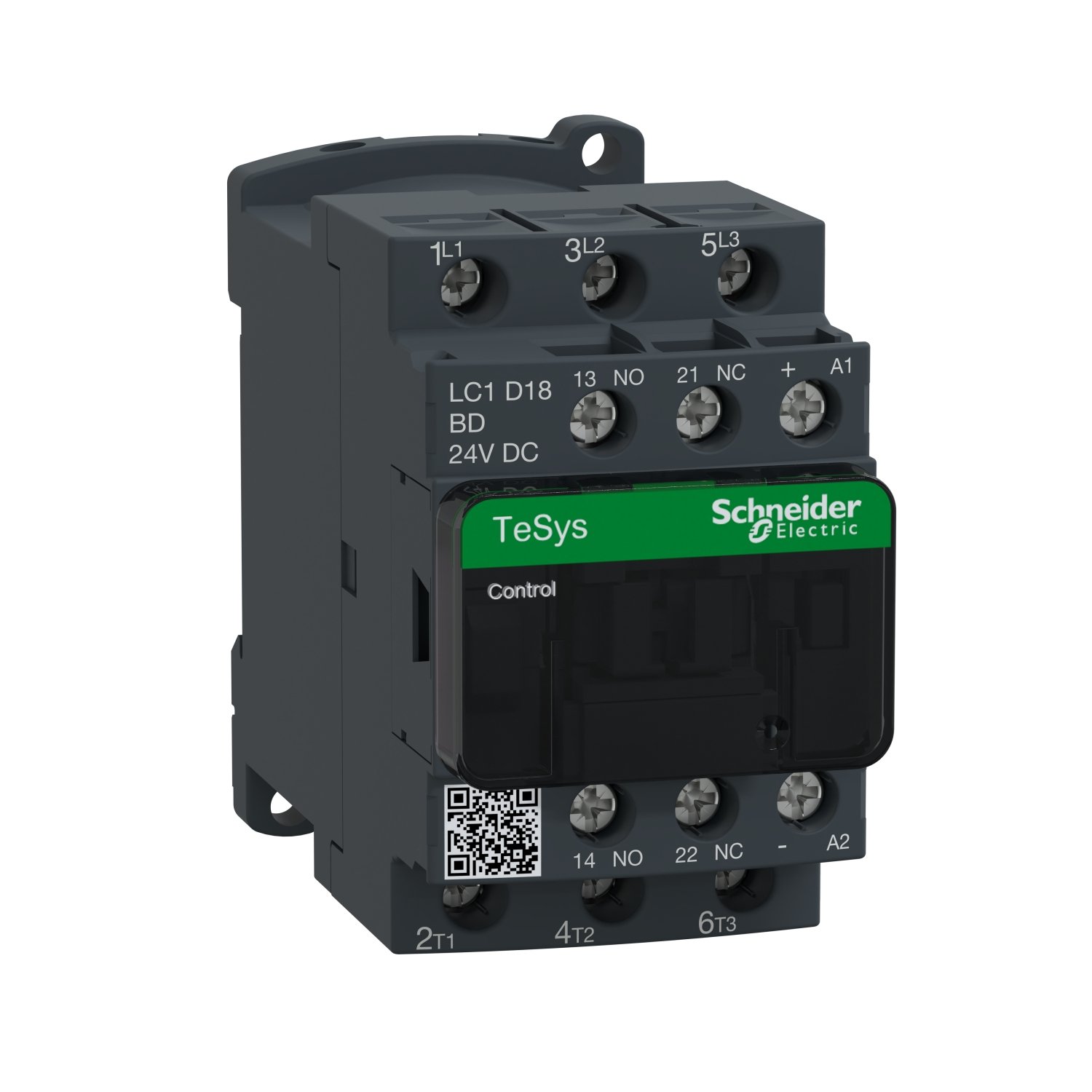

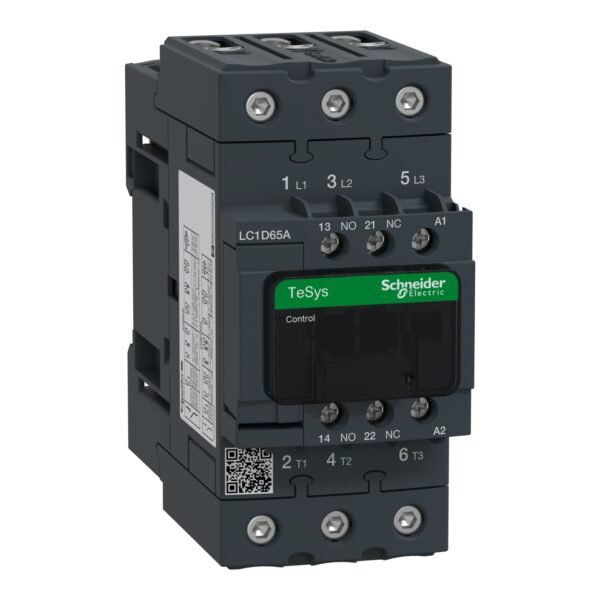
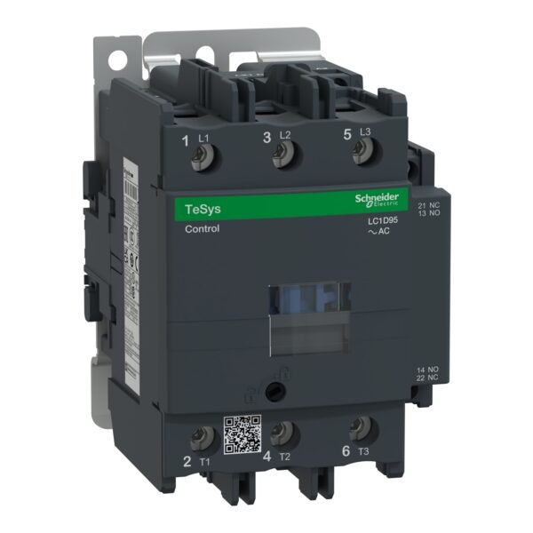
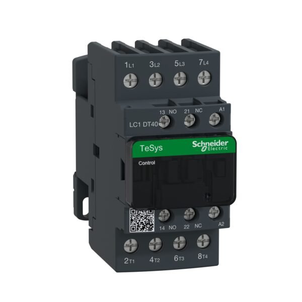
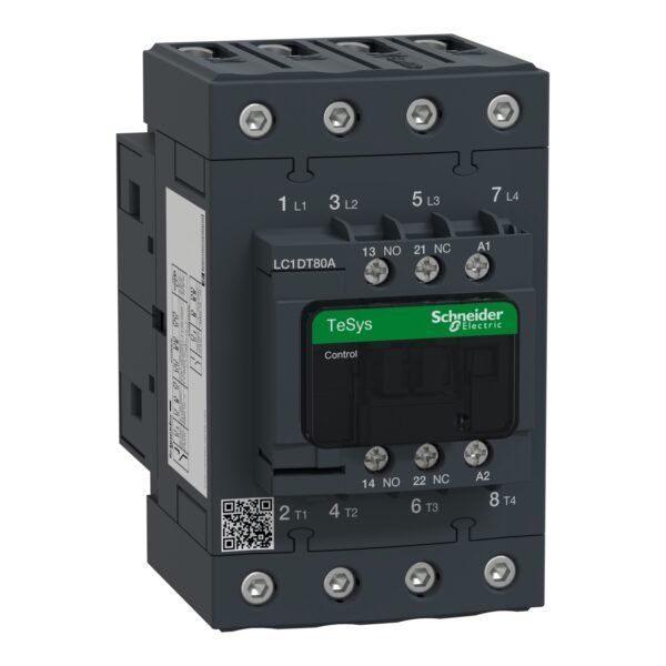
Schneider LC1D18BD Contactor | TeSys D – 3P(3 NO) – AC-3 – <= 440 V 18 A – 24 V DC coil
Schneider LC1D18BD Contactor
Original price was: EGP 5,553.82.EGP 3,004.90Current price is: EGP 3,004.90.
Description
Schneider LC1D18BD Contactor: A Comprehensive Guide
Introduction
In this digital era, electrical systems play a pivotal role in various industries. Among the essential components of these systems is the contactor. Schneider Electric, a renowned name in the electrical industry, offers a wide range of contactors, including the LC1D18BD model. Let’s delve into the intricacies of the Schneider LC1D18BD contactor and understand its significance in electrical applications.
Understanding Contactor Basics
Before diving into specifics, let’s grasp the fundamentals of contactors. A contactor is an electromechanical device used to control the flow of electricity in a circuit. It consists of contacts that open and close to allow or interrupt the electrical current. Contactors are commonly employed in industrial and commercial settings to manage heavy loads efficiently.
Features of Schneider LC1D18BD Contactor
The Schneider LC1D18BD contactor boasts several features that set it apart. With its compact design and high-performance capabilities, it’s ideal for a variety of applications. Some notable features include:
- Compact Design: Despite its robust functionality, the LC1D18BD contactor is designed to occupy minimal space, making it suitable for installations where space is limited.
- High Switching Capacity: This contactor can handle heavy loads with ease, thanks to its high switching capacity, ensuring reliable performance even in demanding environments.
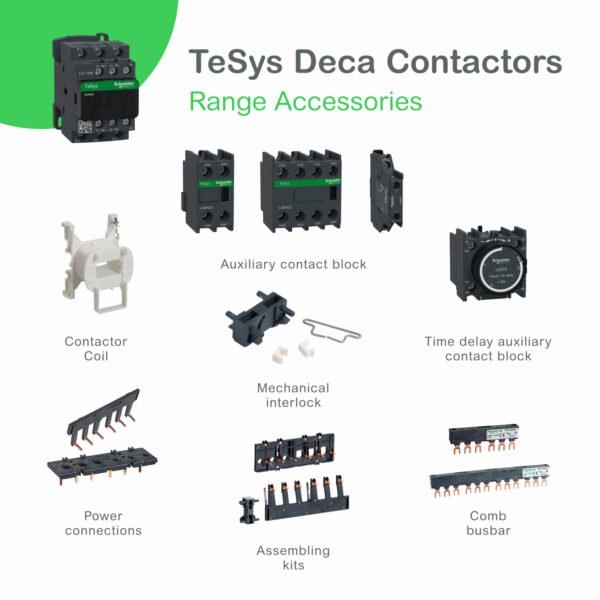
- Built-in Auxiliary Contacts: The LC1D18BD model comes equipped with auxiliary contacts, allowing for enhanced control and monitoring of electrical circuits.
- Coil Voltage Options: Schneider Electric offers a range of coil voltage options for the LC1D18BD contactor, providing flexibility to suit various voltage requirements.
Applications of Schneider LC1D18BD Contactor
The versatility of the Schneider LC1D18BD contactor makes it suitable for a wide range of applications, including:
- Motor control in industrial machinery
- HVAC systems
- Lighting control
- Elevator systems
- Conveyor belts
- And more
Installation Process
Installing the Schneider LC1D18BD contactor is straightforward, but it’s crucial to follow the manufacturer’s guidelines to ensure proper operation and safety. Here’s a basic outline of the installation process:
- Selecting the Mounting Location: Choose a suitable location for installing the contactor, considering factors such as accessibility and ventilation.
- Wiring Connections: Connect the control circuit wires to the appropriate terminals on the contactor, ensuring proper polarity and tight connections.
- Mounting the Contactor: Secure the contactor in place using the provided mounting screws or brackets.
- Testing: After installation, perform a thorough test to verify the functionality of the contactor and ensure that it operates as expected.
Maintenance Tips
To ensure optimal performance and longevity of the Schneider LC1D18BD contactor, regular maintenance is essential. Here are some maintenance tips to follow:
- Keep it Clean: Periodically clean the contactor to remove dust and debris that can affect its performance.
- Inspect for Wear and Tear: Check the contacts and other components for signs of wear and tear, and replace any damaged parts promptly.
- Tighten Loose Connections: Ensure that all wiring connections are tight to prevent overheating and electrical faults.
Troubleshooting Common Issues
Despite its reliability, the Schneider LC1D18BD contactor may encounter occasional issues. Here are some common problems and troubleshooting steps:
- Failure to Energize: Check the power supply and control circuit connections to ensure proper voltage and continuity.
- Overheating: Inspect for any obstructions or poor ventilation around the contactor and address them accordingly.
- Contact Welding: If the contacts become welded due to high current or arcing, replace the contactor to prevent further damage.
Additional information
| brands | Schneider Electric |
|---|


Reviews
There are no reviews yet.