
No products in the cart.
-46%On Sale
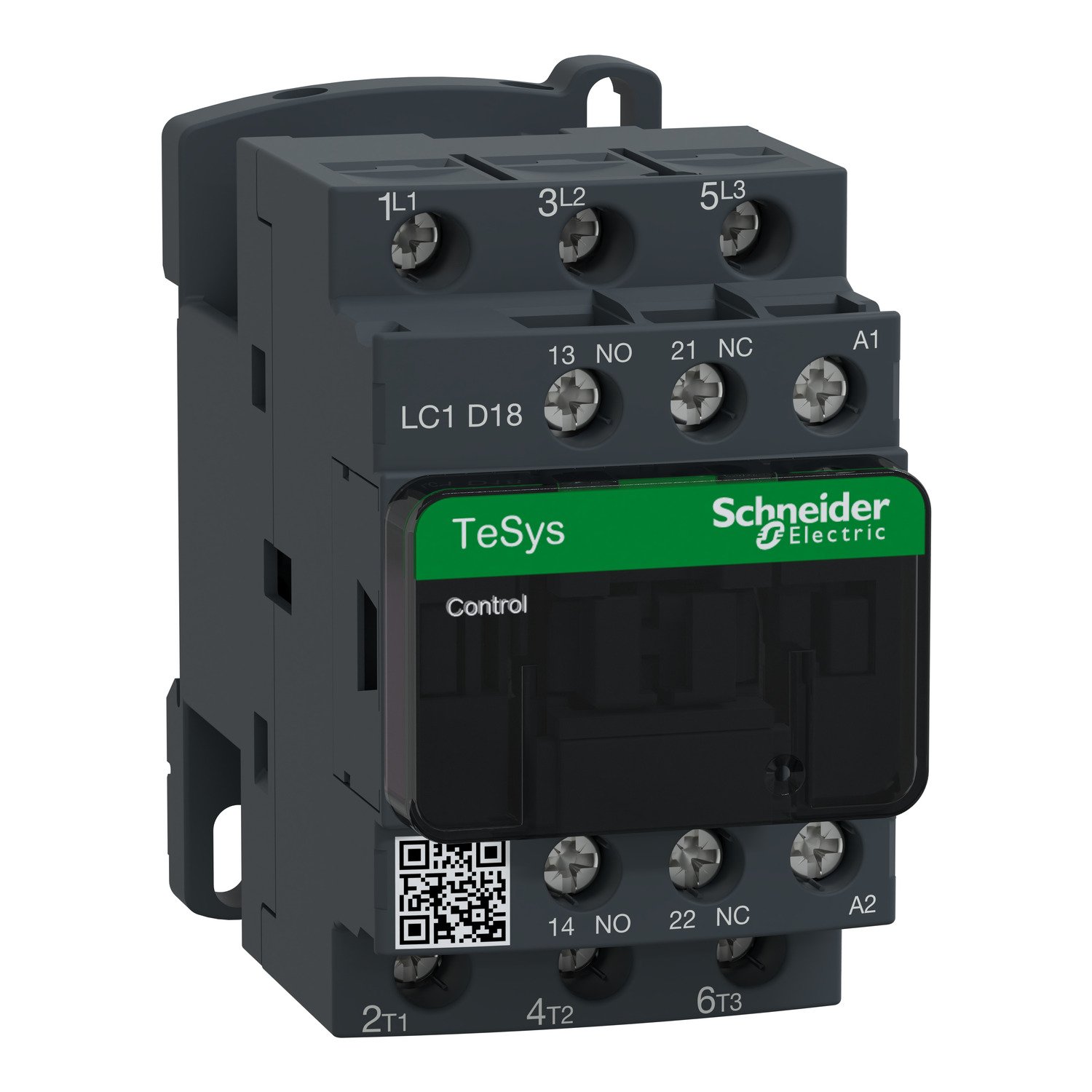
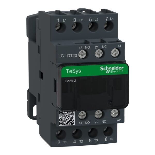
Schneider LC1D18M7 Contactor | TeSys D- 3P(3 NO) – AC-3 – <= 440 V 18 A – 220 V AC coil
Schneider LC1D18M7 Contactor
Original price was: EGP 4,056.28.EGP 2,194.70Current price is: EGP 2,194.70.
Description
Schneider LC1D18M7 Contactor: A Comprehensive Guide
Introduction to Schneider LC1D18M7 Contactor
In the realm of electrical engineering and automation, precision and reliability are paramount. This is where it shines. Designed to manage electrical circuits with precision and efficiency, it is a staple component in numerous industrial and commercial applications.
Understanding Contactor Basics
What is a contactor?
A contactor is an electromechanical device used to make or break electrical connections. It serves as a switch for controlling electrical power circuits, typically in high-power applications.
How does a contactor work?
Contactor operation involves an electromagnetic coil that, when energized, generates a magnetic field, attracting a movable core. This action closes the contacts, allowing electricity to flow through the circuit. When the coil is de-energized, the contacts open, interrupting the flow of electricity.
Features of Schneider LC1D18M7 Contactor
Electrical ratings
The LC1D18M7 boasts impressive electrical ratings, ensuring compatibility with a wide range of applications. From low-voltage to high-voltage systems, this contactor delivers consistent performance.
Coil voltage
With options for various coil voltages, including standard AC and DC voltages, it offers flexibility in design and integration.
Contact configuration
Featuring multiple contact configurations, including normally open (NO) and normally closed (NC) contacts, it adapts to diverse circuit requirements.
Enclosure type
The contactor is available in different enclosure types, such as open-frame and enclosed designs, providing options for different environmental conditions.
Applications of Schneider LC1D18M7 Contactor
Industrial machinery
From conveyor systems to manufacturing equipment, it is a reliable solution for controlling motors and other machinery in industrial settings.
Additional information
| brands | Schneider Electric |
|---|
Specifications
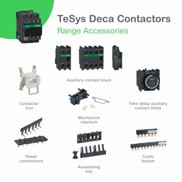
| Range of product | TeSys Deca |
|---|---|
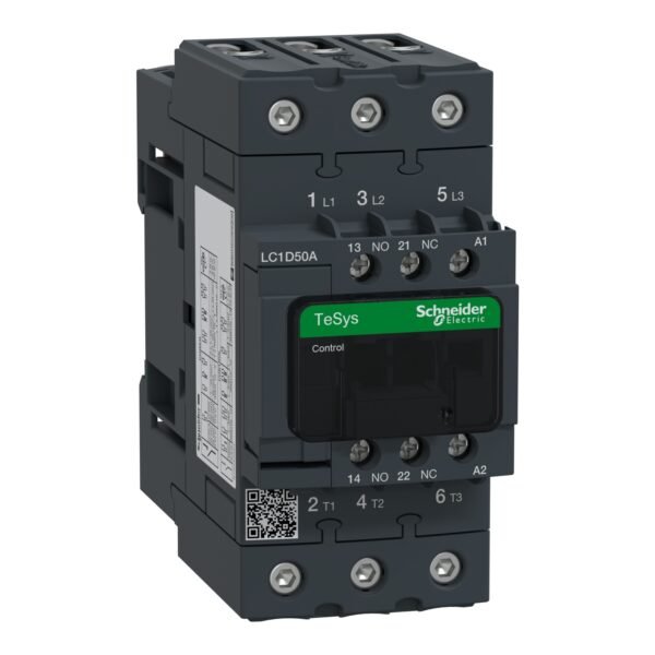
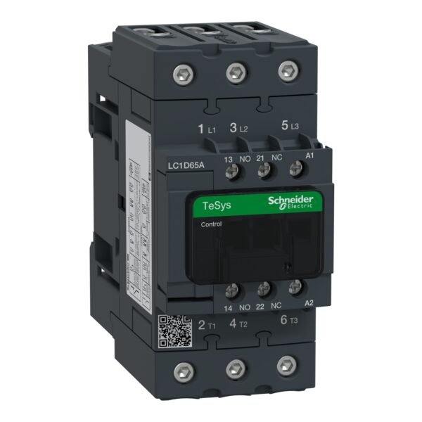
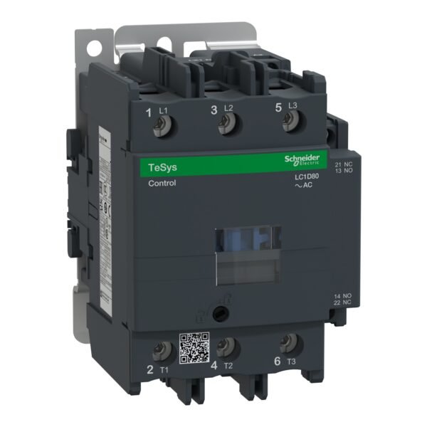
| Product or component type | Contactor |
| Device short name | LC1D |
| Contactor application | Resistive load Motor control |
| Utilisation category | AC-1 AC-4 AC-3 AC-3e |
| Poles description | 3P |
| [Ue] rated operational voltage | Power circuit: <= 690 V AC 25...400 Hz Power circuit: <= 300 V DC |
| [Ie] rated operational current | 18 A (at <60 °C) at <= 440 V AC AC-3 for power circuit 32 A (at <60 °C) at <= 440 V AC AC-1 for power circuit 18 A (at <60 °C) at <= 440 V AC AC-3e for power circuit |
| [Uc] control circuit voltage | 220 V AC 50/60 Hz |
| Motor power kW | 4 kW at 220...230 V AC 50/60 Hz (AC-3) 7.5 kW at 380...400 V AC 50/60 Hz (AC-3) 9 kW at 415...440 V AC 50/60 Hz (AC-3) 10 kW at 500 V AC 50/60 Hz (AC-3) 10 kW at 660...690 V AC 50/60 Hz (AC-3) 4 kW at 400 V AC 50/60 Hz (AC-4) 4 kW at 220...230 V AC 50/60 Hz (AC-3e) 7.5 kW at 380...400 V AC 50/60 Hz (AC-3e) 9 kW at 415...440 V AC 50/60 Hz (AC-3e) 10 kW at 500 V AC 50/60 Hz (AC-3e) 10 kW at 660...690 V AC 50/60 Hz (AC-3e) |
|---|---|
| Motor power hp | 1 hp at 115 V AC 50/60 Hz for 1 phase motors 3 hp at 230/240 V AC 50/60 Hz for 1 phase motors 5 hp at 200/208 V AC 50/60 Hz for 3 phases motors 5 hp at 230/240 V AC 50/60 Hz for 3 phases motors 10 hp at 460/480 V AC 50/60 Hz for 3 phases motors 15 hp at 575/600 V AC 50/60 Hz for 3 phases motors |
| Compatibility code | LC1D |
| Pole contact composition | 3 NO |
| Protective cover | With |
| [Ith] conventional free air thermal current | 10 A (at 60 °C) for signalling circuit 32 A (at 60 °C) for power circuit |
| Irms rated making capacity | 140 A AC for signalling circuit conforming to IEC 60947-5-1 250 A DC for signalling circuit conforming to IEC 60947-5-1 300 A at 440 V for power circuit conforming to IEC 60947 |
| Rated breaking capacity | 300 A at 440 V for power circuit conforming to IEC 60947 |
| [Icw] rated short-time withstand current | 145 A 40 °C - 10 s for power circuit 240 A 40 °C - 1 s for power circuit 40 A 40 °C - 10 min for power circuit 84 A 40 °C - 1 min for power circuit 100 A - 1 s for signalling circuit 120 A - 500 ms for signalling circuit 140 A - 100 ms for signalling circuit |
| Associated fuse rating | 10 A gG for signalling circuit conforming to IEC 60947-5-1 50 A gG at <= 690 V coordination type 1 for power circuit 35 A gG at <= 690 V coordination type 2 for power circuit |
| Average impedance | 2.5 mOhm - Ith 32 A 50 Hz for power circuit |
| Power dissipation per pole | 2.5 W AC-1 0.8 W AC-3 0.8 W AC-3e |
| [Ui] rated insulation voltage | Power circuit: 690 V conforming to IEC 60947-4-1 Power circuit: 600 V CSA certified Power circuit: 600 V UL certified Signalling circuit: 690 V conforming to IEC 60947-1 Signalling circuit: 600 V CSA certified Signalling circuit: 600 V UL certified |
| Overvoltage category | III |
| Pollution degree | 3 |
| [Uimp] rated impulse withstand voltage | 6 kV conforming to IEC 60947 |
| Safety reliability level | B10d = 1369863 cycles contactor with nominal load conforming to EN/ISO 13849-1 B10d = 20000000 cycles contactor with mechanical load conforming to EN/ISO 13849-1 |
| Mechanical durability | 15 Mcycles |
| Electrical durability | 1.65 Mcycles 18 A AC-3 at Ue <= 440 V 1 Mcycles 32 A AC-1 at Ue <= 440 V 1.65 Mcycles 18 A AC-3e at Ue <= 440 V |
| Control circuit type | AC at 50/60 Hz standard |
| Coil technology | Without built-in suppressor module |
| Control circuit voltage limits | 0.3...0.6 Uc (-40…70 °C):drop-out AC 50/60 Hz 0.8...1.1 Uc (-40…60 °C):operational AC 50 Hz 0.85...1.1 Uc (-40…60 °C):operational AC 60 Hz 1...1.1 Uc (60…70 °C):operational AC 50/60 Hz |
| Inrush power in VA | 70 VA 60 Hz cos phi 0.75 (at 20 °C) 70 VA 50 Hz cos phi 0.75 (at 20 °C) |
| Hold-in power consumption in VA | 7.5 VA 60 Hz cos phi 0.3 (at 20 °C) 7 VA 50 Hz cos phi 0.3 (at 20 °C) |
| Heat dissipation | 2…3 W at 50/60 Hz |
| Operating time | 12...22 ms closing 4...19 ms opening |
| Maximum operating rate | 3600 cyc/h 60 °C |
| Maximum operating rate | 3600 cyc/h at 60 °C |
| Connections - terminals | Control circuit: screw clamp terminals 1 1…4 mm² - cable stiffness: flexible without cable end Control circuit: screw clamp terminals 2 1…4 mm² - cable stiffness: flexible without cable end Control circuit: screw clamp terminals 1 1…4 mm² - cable stiffness: flexible with cable end Control circuit: screw clamp terminals 2 1…2.5 mm² - cable stiffness: flexible with cable end Control circuit: screw clamp terminals 1 1…4 mm² - cable stiffness: solid without cable end Control circuit: screw clamp terminals 2 1…4 mm² - cable stiffness: solid without cable end Power circuit: screw clamp terminals 1 1.5…6 mm² - cable stiffness: flexible without cable end Power circuit: screw clamp terminals 2 1.5…6 mm² - cable stiffness: flexible without cable end Power circuit: screw clamp terminals 1 1…6 mm² - cable stiffness: flexible with cable end Power circuit: screw clamp terminals 2 1…4 mm² - cable stiffness: flexible with cable end Power circuit: screw clamp terminals 1 1.5…6 mm² - cable stiffness: solid without cable end Power circuit: screw clamp terminals 2 1.5…6 mm² - cable stiffness: solid without cable end |
| Tightening torque | Power circuit: 1.7 N.m - on screw clamp terminals - with screwdriver flat Ø 6 mm Power circuit: 1.7 N.m - on screw clamp terminals - with screwdriver Philips No 2 Control circuit: 1.7 N.m - on screw clamp terminals - with screwdriver flat Ø 6 mm Control circuit: 1.7 N.m - on screw clamp terminals - with screwdriver Philips No 2 Control circuit: 1.7 N.m - on screw clamp terminals - with screwdriver pozidriv No 2 Power circuit: 1.7 N.m - on screw clamp terminals - with screwdriver pozidriv No 2 |
| Auxiliary contact composition | 1 NO + 1 NC |
| Auxiliary contacts type | type mechanically linked 1 NO + 1 NC conforming to IEC 60947-5-1 type mirror contact 1 NC conforming to IEC 60947-4-1 |
| Signalling circuit frequency | 25...400 Hz |
| Minimum switching voltage | 17 V for signalling circuit |
| Minimum switching current | 5 mA for signalling circuit |
| Insulation resistance | > 10 MOhm for signalling circuit |
| Non-overlap time | 1.5 ms on de-energisation between NC and NO contact 1.5 ms on energisation between NC and NO contact |
| Mounting support | Plate Rail |
| Standards | CSA C22.2 No 14 EN 60947-4-1 EN 60947-5-1 IEC 60947-4-1 IEC 60947-5-1 UL 60947-4-1 IEC 60335-1:Clause 30.2 IEC 60335-2-40:Annex JJ UL 60335-2-40:Annex JJ CSA C22.2 No 60947-4-1 |
|---|---|
| Product certifications | UL CCC CSA Marine UKCA EAC CB Scheme |
| IP degree of protection | IP20 front face conforming to IEC 60529 |
| Protective treatment | TH conforming to IEC 60068-2-30 |
| Climatic withstand | conforming to IACS E10 exposure to damp heat conforming to IEC 60947-1 Annex Q category D exposure to damp heat |
| Permissible ambient air temperature around the device | -40…60 °C 60…70 °C with derating |
| Operating altitude | 0...3000 m |
| Fire resistance | 850 °C conforming to IEC 60695-2-1 |
| Flame retardance | V1 conforming to UL 94 |
| Mechanical robustness | Vibrations contactor open (2 Gn, 5...300 Hz) Vibrations contactor closed (4 Gn, 5...300 Hz) Shocks contactor open (10 Gn for 11 ms) Shocks contactor closed (15 Gn for 11 ms) |
| Height | 77 mm |
| Width | 45 mm |
| Depth | 86 mm |
| Net weight | 0.33 kg |
| Unit Type of Package 1 | PCE |
|---|---|
| Number of Units in Package 1 | 1 |
| Package 1 Height | 5.000 cm |
| Package 1 Width | 9.200 cm |
| Package 1 Length | 11.200 cm |
| Package 1 Weight | 352.000 g |
| Unit Type of Package 2 | S02 |
| Number of Units in Package 2 | 20 |
| Package 2 Height | 15.000 cm |
| Package 2 Width | 30.000 cm |
| Package 2 Length | 40.000 cm |
| Package 2 Weight | 7.415 kg |
| Unit Type of Package 3 | P06 |
| Number of Units in Package 3 | 320 |
| Package 3 Height | 75.000 cm |
| Package 3 Width | 60.000 cm |
| Package 3 Length | 80.000 cm |
| Package 3 Weight | 128.420 kg |
| Warranty | 18 months |
|---|


Reviews
There are no reviews yet.