
No products in the cart.
-46%On Sale
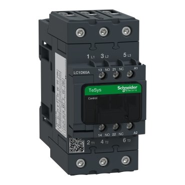
Schneider LC1D65AE7 | IEC contactor, TeSys Deca, nonreversing, 65A, 40HP at 480VAC, up to 100kA SCCR, 3 phase, 3 NO, 48VAC 50/60Hz coil, open
Schneider LC1D65AE7 | IEC contactor, TeSys Deca, nonreversing, 65A, 40HP at 480VAC, up to 100kA SCCR, 3 phase, 3 NO, 48VAC 50/60Hz coil, open
Original price was: EGP 14,286.14.EGP 7,729.50Current price is: EGP 7,729.50.
Description
- Introduction to the Schneider LC1D65AE7 Contactor
- Overview of the role of contactors in motor control and automation.
- Schneider Electric’s reputation in providing reliable contactors for industrial needs.
- Introduction to the LC1D65AE7, highlighting its primary applications and benefits.
- Key Features of the Schneider LC1D65AE7
- High Current Rating: Supports up to 65A for AC-3 motor applications, suitable for moderate to high-power motors.
- Durability and Construction Quality: Engineered for robustness in industrial environments, withstanding frequent use.
- Control Voltage Flexibility: Equipped with a 230V AC coil, making it compatible with standard control voltages.
- Compact, Space-Saving Design: Optimized for control panels where space efficiency is crucial.
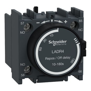
- Integration with Schneider Accessories: Supports various add-ons, such as auxiliary contacts and timers, for expanded functionality.
- Technical Specifications of the LC1D65AE7
- Rated Operational Current: 65A for AC-3 applications, ideal for direct motor starting.
- Coil Voltage: Operates at 230V AC.
- Utilization Categories: Rated for AC-3 category applications, particularly motor control.
- Electrical and Mechanical Endurance: High lifespan even in high-cycle industrial operations.
- Mounting Options: Suitable for both DIN rail and panel mounting for easy installation.
- How the LC1D65AE7 Operates in Motor Control Applications
- Motor Starting and Stopping: Provides reliable control for direct-on-line (DOL) motor starting applications.
- Reduced Maintenance Needs: Designed to minimize wear and tear, providing stable performance under frequent switching.
- Built-In Arc Suppression: Reduces arc formation during switching, extending the lifespan of the contactor and connected equipment.
- Applications and Industry Use Cases
- Industries: Commonly used in sectors like manufacturing, HVAC, water treatment, and energy.
- Compatible Equipment: Well-suited for motors, pumps, compressors, fans, and other motor-driven machinery.
- Benefits for These Use Cases: Enhances equipment longevity, reduces downtime, and improves operational efficiency.
- Installation Guidelines for the Schneider LC1D65AE7
- Safety Considerations: Important safety tips and PPE recommendations for installation.
- Step-by-Step Installation Process: Detailed instructions for mounting and wiring the contactor.
- Connection Tips: Ensuring secure connections and avoiding common wiring issues.
- Testing the Contactor: Pre-operation testing steps to verify proper functionality.
- Benefits of Choosing Schneider Electric Contactors
- Quality and Durability: Known for products that withstand high electrical and mechanical demands.
- Easy System Integration: Compatible with Schneider’s automation and motor control products.
- Global Support: Schneider’s worldwide network ensures product availability and technical assistance.
- Maintenance and Troubleshooting Tips
- Routine Maintenance Checklist: Cleaning, inspection, and functional testing tips.
- Troubleshooting Common Issues: Solutions for issues like inconsistent contactor operation and coil failures.
- Extending the Device’s Lifespan: Practices for optimizing performance and durability.
- Where to Buy the Schneider LC1D65AE7
- Authorized Distributors: Recommended sources for authentic products.
- Reliable Online Retailers: Tips on identifying genuine Schneider products from online stores.
- Bulk Purchasing Options: Information for large-scale projects requiring multiple units.
- Conclusion: Is the Schneider LC1D65AE7 Right for You?
- Summary of the LC1D65AE7’s features, specifications, and ideal use cases.
- Final thoughts on choosing the right contactor for your motor control requirements.
Additional information
| brands | Schneider Electric |
|---|
Specifications
| Range | TeSys TeSys Deca |
|---|---|
| Range of Product | TeSys Deca |
| Product or Component Type | Contactor |
| Device short name | LC1D |
| contactor application | Motor control Resistive load |
| Utilisation category | AC-4 AC-1 AC-3 AC-3e |
| poles description | 3P |
| [Ue] rated operational voltage | Power circuit <= 690 V AC 25...400 Hz Power circuit <= 300 V DC |
| [Ie] rated operational current | 80 A (at <140 °F (60 °C)) at <= 440 V AC AC-1 for power circuit 65 A (at <140 °F (60 °C)) at <= 440 V AC AC-3 for power circuit 65 A (at <140 °F (60 °C)) at <= 440 V AC AC-3e for power circuit |
| [Uc] control circuit voltage | 48 V AC 50/60 Hz |
| Motor power kW | 11 kW at 400 V AC 50/60 Hz (AC-4) 18.5 kW at 220...230 V AC 50/60 Hz (AC-3) 30 kW at 380...400 V AC 50/60 Hz (AC-3) 37 kW at 500 V AC 50/60 Hz (AC-3) 37 kW at 660...690 V AC 50/60 Hz (AC-3) 18.5 kW at 220...230 V AC 50/60 Hz (AC-3e) 30 kW at 380...400 V AC 50/60 Hz (AC-3e) 37 kW at 500 V AC 50/60 Hz (AC-3e) 37 kW at 660...690 V AC 50/60 Hz (AC-3e) |
|---|---|
| Maximum Horse Power Rating | 40 hp at 460/480 V AC 50/60 Hz for 3 phase motors 5 hp at 115 V AC 50/60 Hz for 1 phase motors 10 hp at 230/240 V AC 50/60 Hz for 1 phase motors 20 hp at 200/208 V AC 50/60 Hz for 3 phase motors 20 hp at 230/240 V AC 50/60 Hz for 3 phase motors 50 hp at 575/600 V AC 50/60 Hz for 3 phase motors |
| Compatibility code | LC1D |
| Pole contact composition | 3 NO |
| Protective cover | With |
| [Ith] conventional free air thermal current | 10 A (at 140 °F (60 °C)) for signalling circuit 80 A (at 140 °F (60 °C)) for power circuit |
| Irms rated making capacity | 140 A AC for signalling circuit conforming to IEC 60947-5-1 250 A DC for signalling circuit conforming to IEC 60947-5-1 1000 A at 440 V for power circuit conforming to IEC 60947 |
| Rated breaking capacity | 1000 A at 440 V for power circuit conforming to IEC 60947 |
| [Icw] rated short-time withstand current | 640 A 104 °F (40 °C) - 10 s for power circuit 900 A 104 °F (40 °C) - 1 s for power circuit 110 A 104 °F (40 °C) - 10 min for power circuit 260 A 104 °F (40 °C) - 1 min for power circuit 100 A - 1 s for signalling circuit 120 A - 500 ms for signalling circuit 140 A - 100 ms for signalling circuit |
| Associated fuse rating | 10 A gG for signalling circuit conforming to IEC 60947-5-1 125 A gG at <= 690 V coordination type 1 for power circuit 125 A gG at <= 690 V coordination type 2 for power circuit |
| Average impedance | 1.5 mOhm - Ith 80 A 50 Hz for power circuit |
| Power dissipation per pole | 9.6 W AC-1 6.3 W AC-3 6.3 W AC-3e |
| [Ui] rated insulation voltage | Power circuit 600 V CSA Power circuit 600 V UL Signalling circuit 690 V IEC 60947-1 Signalling circuit 600 V CSA Signalling circuit 600 V UL Power circuit 690 V IEC 60947-4-1 |
| Overvoltage category | III |
| Pollution degree | 3 |
| [Uimp] rated impulse withstand voltage | 6 kV IEC 60947 |
| Safety reliability level | B10d = 1369863 cycles contactor with nominal load EN/ISO 13849-1 B10d = 20000000 cycles contactor with mechanical load EN/ISO 13849-1 |
| Mechanical durability | 6 Mcycles |
| Electrical durability | 1.4 Mcycles 80 A AC-1 <= 440 V 1.45 Mcycles 65 A AC-3 <= 440 V 1.45 Mcycles 65 A AC-3e <= 440 V |
| Control circuit type | AC 50/60 Hz standard |
| Coil technology | Without built-in suppressor module |
| Control circuit voltage limits | 0.3...0.6 Uc -40…158 °F (-40…70 °C) drop-out AC 50/60 Hz 0.8...1.1 Uc -40…140 °F (-40…60 °C) operational AC 50 Hz 0.85...1.1 Uc -40…140 °F (-40…60 °C) operational AC 60 Hz 1...1.1 Uc 140…158 °F (60…70 °C) operational AC 50/60 Hz |
| Inrush power in VA | 140 VA 60 Hz cos phi 0.75 (at 68 °F (20 °C)) 160 VA 50 Hz cos phi 0.75 (at 68 °F (20 °C)) |
| Hold-in power consumption in VA | 13 VA 60 Hz cos phi 0.3 (at 68 °F (20 °C)) 15 VA 50 Hz cos phi 0.3 (at 68 °F (20 °C)) |
| Heat dissipation | 4…5 W at 50/60 Hz |
| Operating time | 4...19 ms opening 12...26 ms closing |
| Maximum operating rate | 3600 cyc/h 140 °F (60 °C) |
| Connections - terminals | Control circuit: screw clamp terminals 2 0.002…0.004 in² (1…2.5 mm²) - cable stiffness: flexible with cable end Control circuit: screw clamp terminals 1 0.002…0.006 in² (1…4 mm²) - cable stiffness: flexible without cable end Control circuit: screw clamp terminals 2 0.002…0.006 in² (1…4 mm²) - cable stiffness: flexible without cable end Control circuit: screw clamp terminals 1 0.002…0.006 in² (1…4 mm²) - cable stiffness: flexible with cable end Control circuit: screw clamp terminals 1 0.002…0.006 in² (1…4 mm²) - cable stiffness: solid without cable end Control circuit: screw clamp terminals 2 0.002…0.006 in² (1…4 mm²) - cable stiffness: solid without cable end Power circuit: screw connection 1 0.002…0.05 in² (1…35 mm²) - cable stiffness: flexible without cable end Power circuit: screw connection 2 0.002…0.04 in² (1…25 mm²) - cable stiffness: flexible without cable end Power circuit: screw connection 1 0.002…0.05 in² (1…35 mm²) - cable stiffness: flexible with cable end Power circuit: screw connection 2 0.002…0.04 in² (1…25 mm²) - cable stiffness: flexible with cable end Power circuit: screw connection 1 0.002…0.05 in² (1…35 mm²) - cable stiffness: solid without cable end Power circuit: screw connection 2 0.002…0.04 in² (1…25 mm²) - cable stiffness: solid without cable end |
| Tightening torque | Control circuit 15.05 lbf.in (1.7 N.m) EverLink BTR screw connectors flat Ø 6 mm Control circuit 15.05 lbf.in (1.7 N.m) EverLink BTR screw connectors Philips No 2 Power circuit 70.8 lbf.in (8 N.m) EverLink BTR screw connectors 0.04…0.05 in² (25…35 mm²) hexagonal 0.2 in (4 mm) Power circuit 44.3 lbf.in (5 N.m) EverLink BTR screw connectors 0.002…0.04 in² (1…25 mm²) hexagonal 0.2 in (4 mm) Control circuit 15.05 lbf.in (1.7 N.m) EverLink BTR screw connectors pozidriv No 2 Power circuit 22.1 lbf.in (2.5 N.m) EverLink BTR screw connectors pozidriv No 2 |
| Auxiliary contact composition | 1 NO + 1 NC |
| Auxiliary contacts type | Mechanically linked 1 NO + 1 NC IEC 60947-5-1 Mirror contact 1 NC IEC 60947-4-1 |
| Signalling circuit frequency | 25...400 Hz |
| Minimum switching voltage | 17 V for signalling circuit |
| Minimum switching current | 5 mA for signalling circuit |
| Insulation resistance | > 10 MOhm for signalling circuit |
| Non-overlap time | 1.5 ms on de-energisation between NC and NO contact 1.5 ms on energisation between NC and NO contact |
| Mounting Support | Plate Rail |
| Standards | CSA C22.2 No 14 EN 60947-4-1 EN 60947-5-1 IEC 60947-4-1 IEC 60947-5-1 UL 508 IEC 60335-1 |
|---|---|
| Product Certifications | CSA CCC GOST UL |
| IP degree of protection | IP20 front face IEC 60529 |
| Protective treatment | THIEC 60068-2-30 |
| Climatic withstand | IACS E10 exposure to damp heat IEC 60947-1 Annex Q category D exposure to damp heat |
| Permissible ambient air temperature around the device | -40…140 °F (-40…60 °C) 140…158 °F (60…70 °C) with derating |
| Operating altitude | 0...9842.52 ft (0...3000 m) |
| Fire resistance | 1562 °F (850 °C) IEC 60695-2-1 |
| Flame retardance | V1 conforming to UL 94 |
| Mechanical robustness | Vibrations contactor open 2 Gn, 5...300 Hz) Vibrations contactor closed 4 Gn, 5...300 Hz) Shocks contactor closed 15 Gn for 11 ms) Shocks contactor open 10 Gn for 11 ms) |
| Height | 4.8 in (122 mm) |
| Width | 2.2 in (55 mm) |
| Depth | 4.7 in (120 mm) |
| Net Weight | 1.90 lb(US) (0.86 kg) |
| Category | US10I1222357 |
|---|---|
| Discount Schedule | 0I12 |
| GTIN | 3389119408967 |
| Returnability | No |
| Country of origin | ID |
| Unit Type of Package 1 | PCE |
|---|---|
| Number of Units in Package 1 | 1 |
| Package 1 Height | 2.4 in (6.2 cm) |
| Package 1 Width | 5.3 in (13.5 cm) |
| Package 1 Length | 6.0 in (15.2 cm) |
| Package 1 Weight | 32.7 oz (926.0 g) |
| Unit Type of Package 2 | S02 |
| Number of Units in Package 2 | 10 |
| Package 2 Height | 5.9 in (15.0 cm) |
| Package 2 Width | 11.8 in (30.0 cm) |
| Package 2 Length | 15.7 in (40.0 cm) |
| Package 2 Weight | 22.040 lb(US) (9.997 kg) |
| Unit Type of Package 3 | P06 |
| Number of Units in Package 3 | 160 |
| Package 3 Height | 30.3 in (77.0 cm) |
| Package 3 Width | 31.5 in (80.0 cm) |
| Package 3 Length | 23.6 in (60.0 cm) |
| Package 3 Weight | 369.19 lb(US) (167.46 kg) |
| Warranty | 18 months |
|---|


Reviews
There are no reviews yet.