
No products in the cart.
-42%On Sale
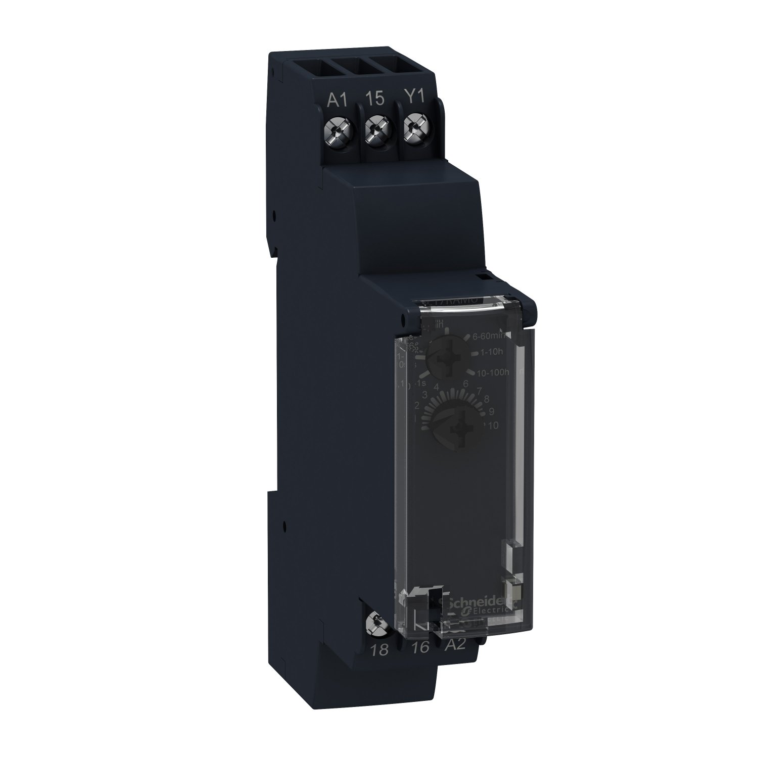
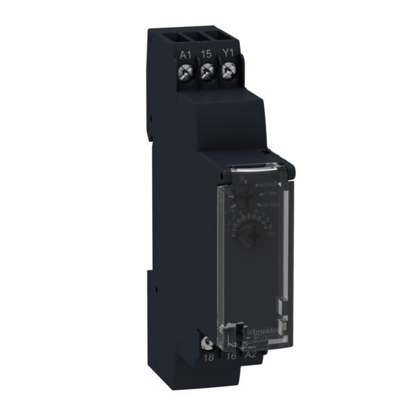
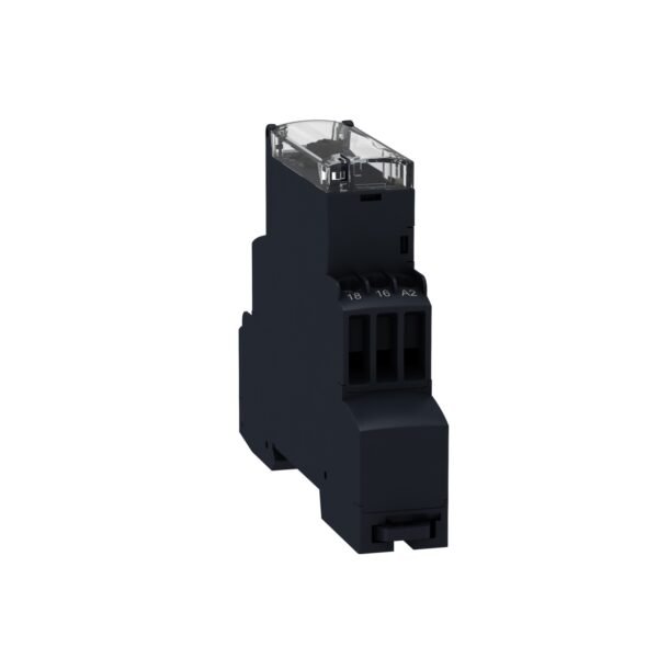
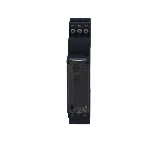
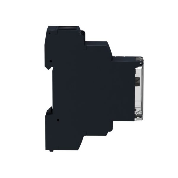
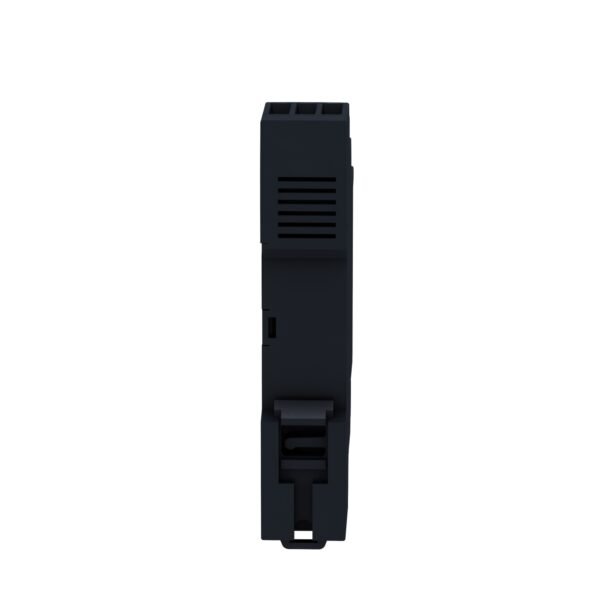
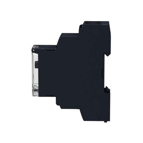
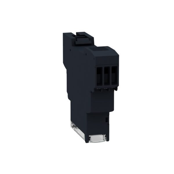
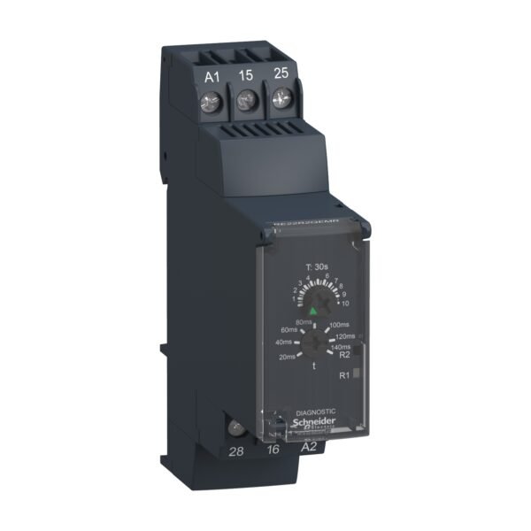
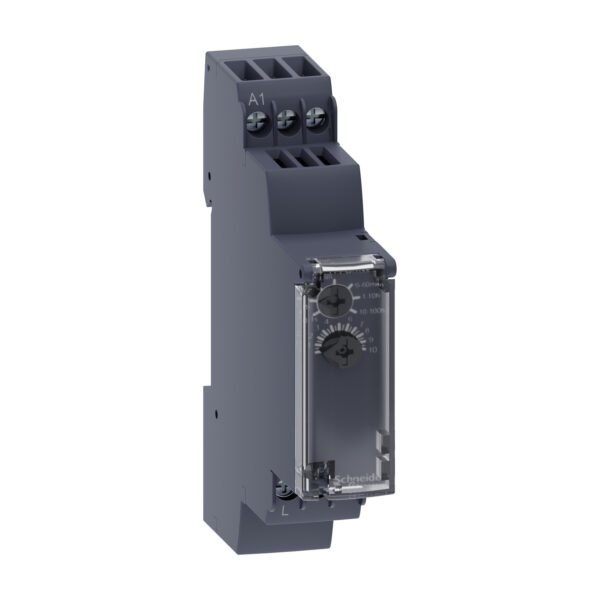
Schneider RE17RBMU | Timing on impulse, one shot timing relay – 1 s..100 h – 24..240 V AC – 1 OC
Original price was: EGP 29,354.00.EGP 17,026.00Current price is: EGP 17,026.00.
Description
Schneider RE17RBMU | Timing on impulse, one shot timing relay – 1 s..100 h – 24..240 V AC – 1 OC
Introduction
In the realm of industrial automation, precise timing is crucial. The Schneider RE17RBMU timing relay stands out as a reliable solution for managing timing functions across a wide range of applications. This article delves into its features, functions, and how it fits into various industrial setups.
What is a Timing Relay?
Timing relays are electromechanical devices used to control the timing of an event based on preset parameters. They find extensive use in industries where time-sensitive operations are common, such as manufacturing, process control, and automation.
Purpose and Function
The primary purpose of the RE17RBMU timing relay is to provide accurate timing control within a specified range, from 1 second to 100 hours. This level of precision ensures that critical processes are executed with the desired timing accuracy, improving overall efficiency and productivity.
Features
- Wide timing range from 1 s to 100 h.
- Compatible with 24 V to 240 V AC power supply.
- Offers 1 OC (open collector) output.
- Compact design for easy integration into control panels.
- LED indicators for status monitoring.
Applications
The RE17RBMU relay finds applications in various industries:
- Automated machinery control.
- Lighting and HVAC systems.
- Motor and pump control.
- Process timing in industrial processes.
Understanding RE17RBMU
The RE17RBMU timing relay operates on the principle of timing on impulse, allowing for precise one-shot timing functions. It is designed to withstand industrial environments, ensuring reliability even in challenging conditions.
Technical Specifications
- Timing Range: 1 second to 100 hours.
- Voltage Compatibility: 24 V AC to 240 V AC.
- Output: 1 OC output.
- Mounting: DIN rail mounting.
- Dimensions: Compact design for space-saving installation.
Installation Guide
Installing the RE17RBMU relay involves:
- Ensure power is turned off.
- Mount the relay securely on a DIN rail.
- Connect input and output wires as per the manual.
Setting Up
Programming the relay for specific timing functions is straightforward using the provided interface. Follow the user manual for step-by-step instructions on setting up desired timing parameters.
Troubleshooting
Common issues like incorrect wiring or parameter settings can be addressed by referring to the troubleshooting section of the manual. Always follow safety protocols when troubleshooting electrical equipment.
Maintenance Tips
To ensure optimal performance:
- Regularly inspect for loose connections.
- Keep the relay clean and free from debris.
- Follow recommended maintenance schedules.
Conclusion
The Schneider RE17RBMU timing relay offers precise timing control essential for various industrial applications. Its robust design, wide compatibility, and user-friendly interface make it a valuable asset in automation and control systems.
FAQs
- Is the RE17RBMU relay suitable for outdoor use? Yes, it is designed to withstand industrial environments, including outdoor conditions.
- Can I adjust the timing range on the relay? Yes, the relay allows adjustment within the specified timing range for flexibility in applications.
- Does it support multiple output configurations? The RE17RBMU typically comes with 1 OC output, suitable for many applications. For multiple outputs, consider other models or external relays.
- What are the common safety precautions when working with timing relays? Always disconnect power before installation or maintenance. Follow electrical safety guidelines and use appropriate personal protective equipment.
- Can the relay be integrated into existing control systems? Yes, it is designed for easy integration into control panels and existing automation setups.
Additional information
| brands | Schneider Electric |
|---|


Reviews
There are no reviews yet.