
No products in the cart.
-42%On Sale
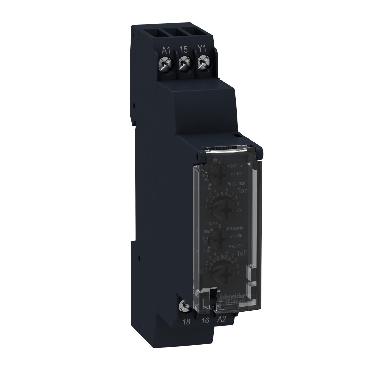
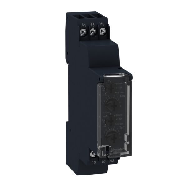
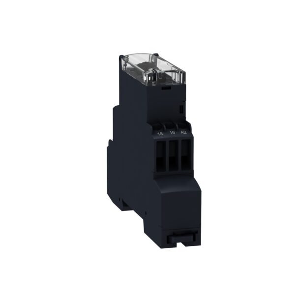
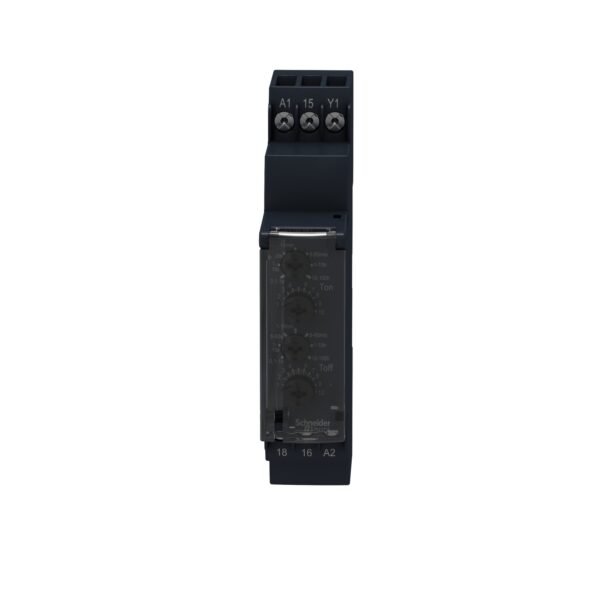
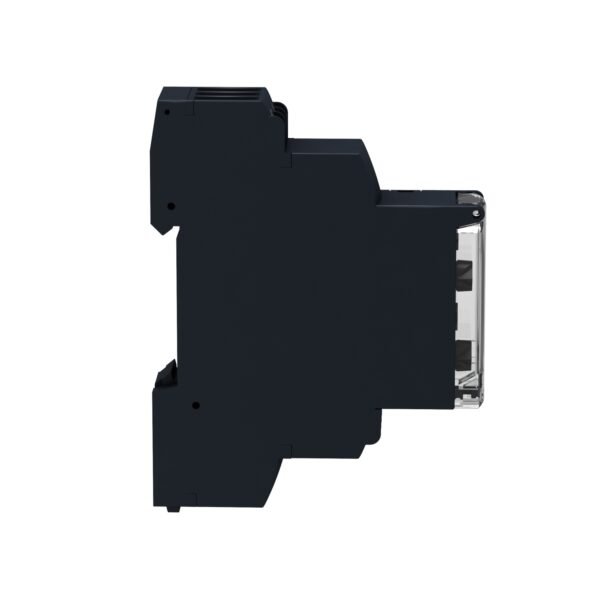
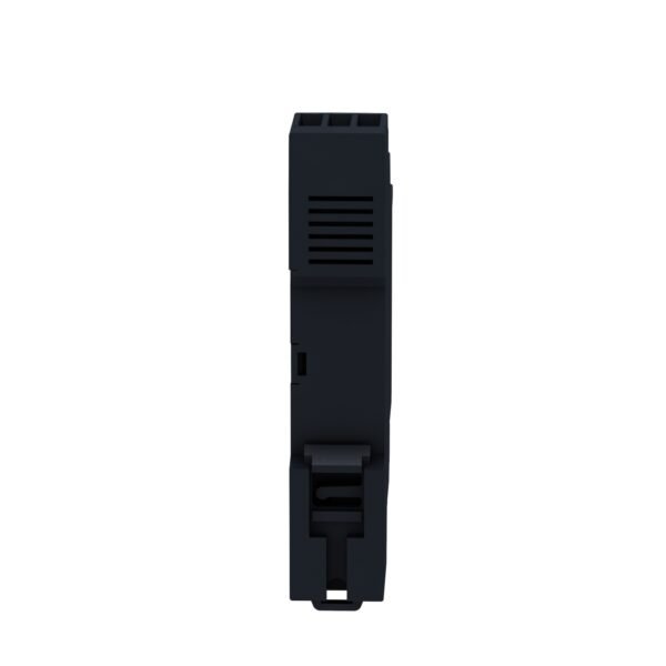
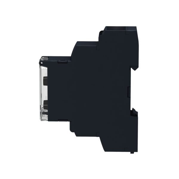
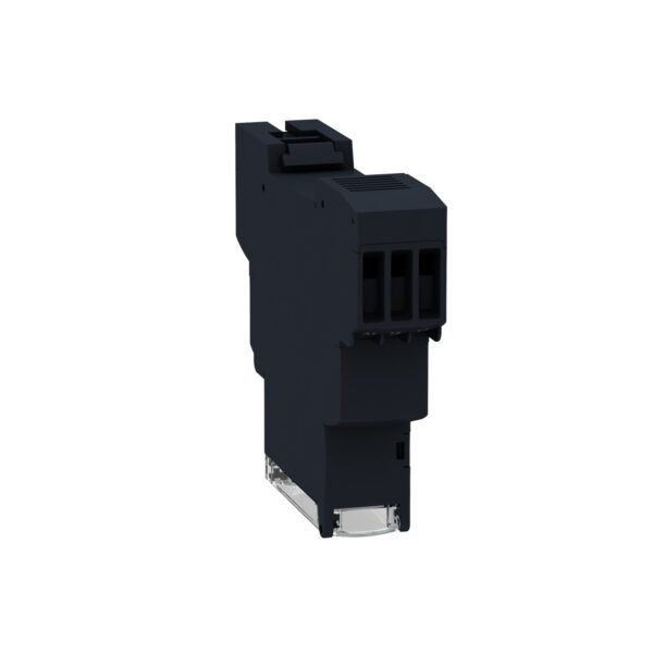
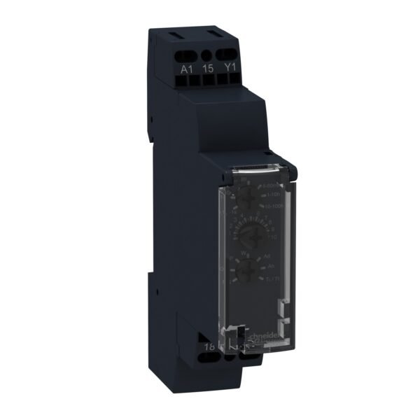
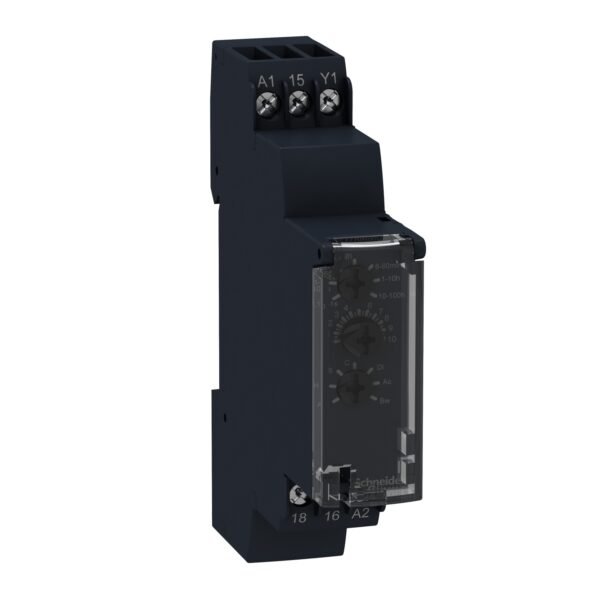
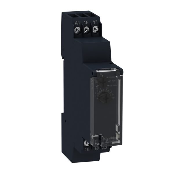
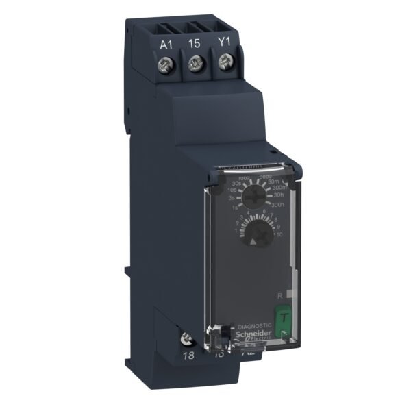
Schneider RE17RLMU | Asymmetrical flashing relay – 1 s..100 h – 24..240 V AC – 1 OC
Original price was: EGP 2,588.00.EGP 1,501.00Current price is: EGP 1,501.00.
Description
Schneider RE17RLMU | Asymmetrical flashing relay – 1 s..100 h – 24..240 V AC – 1 OC
Introduction
The Schneider RE17RLMU is a cutting-edge asymmetrical flashing relay designed to provide precise control over timing functions in electrical circuits. Its versatility and reliability make it a preferred choice among professionals in the electrical engineering field.
Functionality
This relay operates by alternating the on/off cycle of a connected electrical load, allowing for customizable flashing intervals ranging from 1 second to 100 hours. This level of control is vital in applications where precise timing is required, such as industrial automation, lighting systems, and equipment monitoring.
Technical Specs
The RE17RLMU supports a wide voltage range from 24V AC to 240V AC, with a single output contact (1 OC) for seamless integration into diverse circuit setups. Its compact design and DIN rail mounting make it suitable for both new installations and retrofitting projects.
Applications
This relay finds extensive use in scenarios where intermittent operation or flashing signals are necessary. Examples include traffic signal control, elevator systems, conveyor belts, and HVAC (Heating, Ventilation, and Air Conditioning) units.
Advantages
One of the key advantages of the Schneider RE17RLMU is its ability to enhance energy efficiency by controlling the duration of electrical loads. This not only reduces power consumption but also extends the lifespan of connected devices.
Installation
Installing the RE17RLMU relay is straightforward, thanks to its user-friendly design and clear labeling of terminals. However, it is crucial to follow manufacturer guidelines and safety protocols during installation to ensure optimal performance and safety.
Troubleshooting
Despite its reliability, occasional issues may arise with the RE17RLMU relay. Common problems include erratic flashing patterns or failure to operate as expected. Troubleshooting steps may involve checking wiring connections, power supply integrity, and programming settings.
Maintenance
Regular maintenance is essential to keep the Schneider RE17RLMU relay operating smoothly. This includes periodic inspection of connections, cleaning of terminals, and updating firmware if applicable. Proper maintenance not only prevents downtime but also prolongs the relay’s lifespan.
Conclusion
In conclusion, the Schneider RE17RLMU asymmetrical flashing relay offers a sophisticated solution for precise timing control in electrical systems. Its advanced features, ease of installation, and versatility make it a valuable asset across various industries.
FAQs
- Can the flashing interval of the RE17RLMU be adjusted on the fly?
- No, the flashing interval needs to be programmed beforehand using the relay’s settings.
- Is the RE17RLMU suitable for outdoor applications?
- Yes, it is designed to withstand a wide temperature range and is suitable for outdoor use with proper protection.
- What is the typical lifespan of the RE17RLMU relay?
- With regular maintenance and proper usage, the relay can last for several years.
- Can multiple RE17RLMU relays be synchronized for coordinated flashing operations?
- Yes, multiple relays can be synchronized for synchronized flashing sequences.
- Does the RE17RLMU have built-in surge protection?
- Yes, it is equipped with surge protection to safeguard against electrical spikes and surges.
Additional information
| brands | Schneider Electric |
|---|

Reviews
There are no reviews yet.