
No products in the cart.


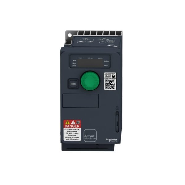
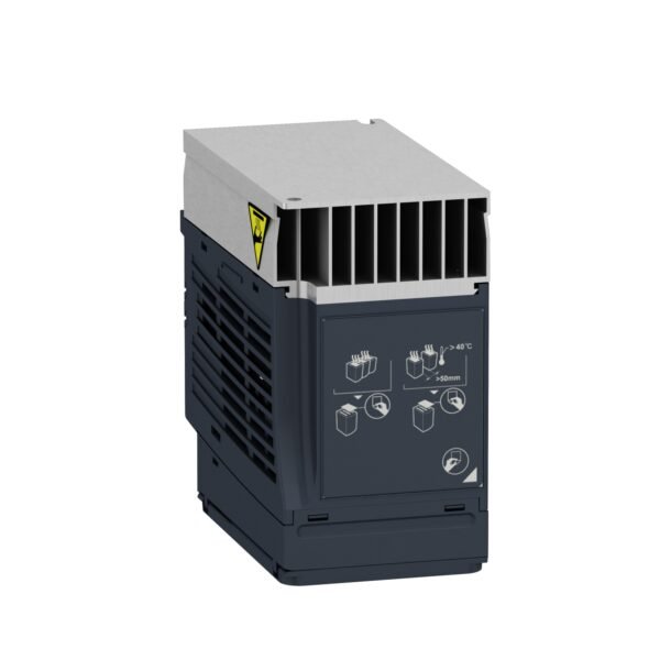
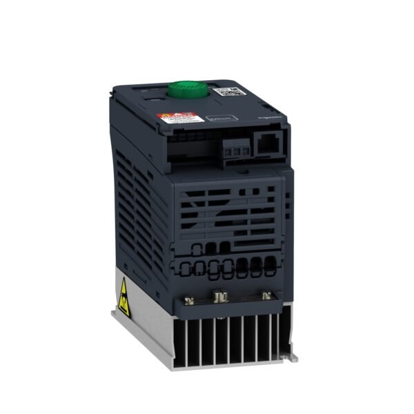
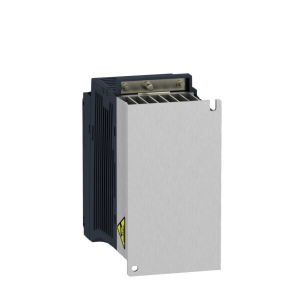

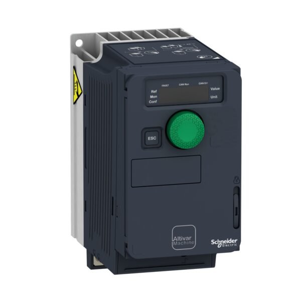
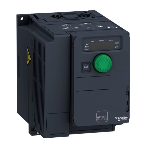
Schneider ATV320U06M2C | Variable speed drive, ATV320, 0.55 kW, 200…240 V, 1 phase, compact
Schneider ATV320U06M2C | Variable speed drive, ATV320, 0.55 kW, 200…240 V, 1 phase, compact
EGP 21,147.00
Description
1. Introduction to Schneider ATV320U06M2C
Schneider Electric, a renowned name in the electrical industry, introduces it as part of its advanced VSD lineup. It is engineered to enhance motor control efficiency and reduce energy consumption, making it an ideal choice for industries striving for operational excellence.
2. Understanding Variable Speed Drives (VSDs)
Variable speed drives, also known as adjustable frequency drives (AFDs), play a crucial role in regulating motor speed by adjusting the frequency and voltage supplied to the motor. This functionality allows for precise control over processes, leading to energy savings and improved performance.
3. Features of the ATV320U06M2C
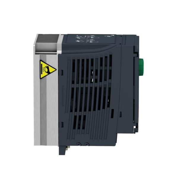
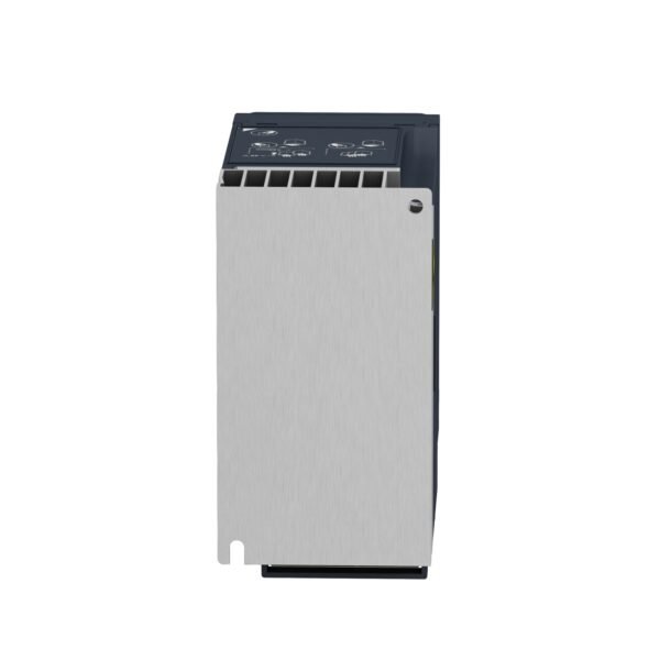
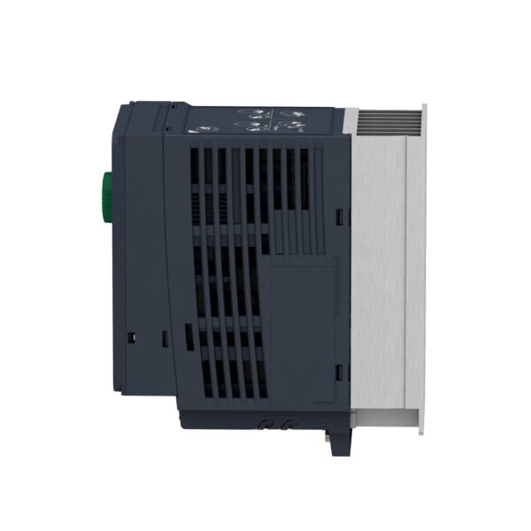
- Compact design for space-saving installation
- High-performance control algorithms for smooth operation
- Integrated safety functions for enhanced protection
- User-friendly interface for easy configuration and monitoring
4. Technical Specifications
Power and Voltage
it operates at 0.55 kW with a voltage range of 200 to 240 volts.
Phases and Compact Design
It is designed for single-phase applications, making it suitable for a wide range of installations where space is limited.
5. Benefits of Using Schneider ATV320U06M2C
- Energy Efficiency: Reduces energy consumption by adjusting motor speed according to demand.
- Cost Savings: Optimizes motor performance, leading to reduced operating costs.
- Enhanced Control: Provides precise control over processes, improving productivity.
6. Applications in Various Industries
The ATV320U06M2C finds applications in industries such as:
- HVAC (Heating, Ventilation, and Air Conditioning)
- Pumping systems
- Conveyors
- Manufacturing processes
7. Installation and Setup Guide
A detailed installation and setup guide accompanies the ATV320U06M2C, ensuring smooth integration into existing systems.
8. Maintenance Tips
Regular maintenance is essential for optimal performance. Follow manufacturer guidelines for inspections and servicing.
9. Comparison with Other Variable Speed Drives
Compare the ATV320U06M2C with other VSDs to understand its unique features and advantages.
10. Customer Reviews and Testimonials
Explore real-world experiences of users to gain insights into the performance and reliability of the ATV320U06M2C.
11. Future Developments and Upgrades
Stay informed about future developments and upgrades in Schneider’s VSD lineup for continuous improvement.
12. Conclusion
The Schneider ATV320U06M2C stands out as a reliable and efficient variable speed drive, offering precise control, energy savings, and enhanced performance across various applications.
Additional information
| brands | Schneider Electric |
|---|
Specifications
| Range of product | Altivar Machine ATV320 |
|---|---|
| Product or component type | Variable speed drive |
| Product specific application | Complex machines |
| Variant | Standard version |
| Format of the drive | Compact |
| Mounting mode | Wall mount |
| Communication port protocol | Modbus serial CANopen |
| Option card | Communication module, CANopen Communication module, EtherCAT Communication module, Profibus DP V1 Communication module, PROFINET Communication module, Ethernet Powerlink Communication module, EtherNet/IP Communication module, DeviceNet |
| [Us] rated supply voltage | 200...240 V - 15...10 % |
| Nominal output current | 3.7 A |
| Motor power kW | 0.55 kW for heavy duty |
| EMC filter | Class C2 EMC filter integrated |
| IP degree of protection | IP20 |
| Discrete input number | 7 |
|---|---|
| Discrete input type | STO safe torque off, 24 V DC, impedance: 1.5 kOhm DI1...DI6 logic inputs, 24 V DC (30 V) DI5 programmable as pulse input: 0…30 kHz, 24 V DC (30 V) |
| Discrete input logic | Positive logic (source) Negative logic (sink) |
| Discrete output number | 3 |
| Discrete output type | Open collector DQ+ 0…1 kHz 30 V DC 100 mA Open collector DQ- 0…1 kHz 30 V DC 100 mA |
| Analogue input number | 3 |
| Analogue input type | AI1 voltage: 0...10 V DC, impedance: 30 kOhm, resolution 10 bits AI2 bipolar differential voltage: +/- 10 V DC, impedance: 30 kOhm, resolution 10 bits AI3 current: 0...20 mA (or 4-20 mA, x-20 mA, 20-x mA or other patterns by configuration), impedance: 250 Ohm, resolution 10 bits |
| Analogue output number | 1 |
| Analogue output type | Software-configurable current AQ1: 0...20 mA impedance 800 Ohm, resolution 10 bits Software-configurable voltage AQ1: 0...10 V DC impedance 470 Ohm, resolution 10 bits |
| Relay output type | Configurable relay logic R1A 1 NO electrical durability 100000 cycles Configurable relay logic R1B 1 NC electrical durability 100000 cycles Configurable relay logic R1C Configurable relay logic R2A 1 NO electrical durability 100000 cycles Configurable relay logic R2C |
| Maximum switching current | Relay output R1A, R1B, R1C on resistive load, cos phi = 1: 3 A at 250 V AC Relay output R1A, R1B, R1C on resistive load, cos phi = 1: 3 A at 30 V DC Relay output R1A, R1B, R1C, R2A, R2C on inductive load, cos phi = 0.4 and L/R = 7 ms: 2 A at 250 V AC Relay output R1A, R1B, R1C, R2A, R2C on inductive load, cos phi = 0.4 and L/R = 7 ms: 2 A at 30 V DC Relay output R2A, R2C on resistive load, cos phi = 1: 5 A at 250 V AC Relay output R2A, R2C on resistive load, cos phi = 1: 5 A at 30 V DC |
| Minimum switching current | Relay output R1A, R1B, R1C, R2A, R2C: 5 mA at 24 V DC |
| Method of access | Slave CANopen |
| 4 quadrant operation possible | True |
| Asynchronous motor control profile | Voltage/frequency ratio, 5 points Flux vector control without sensor, standard Voltage/frequency ratio - Energy Saving, quadratic U/f Flux vector control without sensor - Energy Saving Voltage/frequency ratio, 2 points |
| Synchronous motor control profile | Vector control without sensor |
| Maximum output frequency | 0.599 kHz |
| Acceleration and deceleration ramps | Linear U S CUS Ramp switching Acceleration/deceleration ramp adaptation Acceleration/deceleration automatic stop with DC injection |
| Motor slip compensation | Automatic whatever the load Adjustable 0...300 % Not available in voltage/frequency ratio (2 or 5 points) |
| Switching frequency | 2...16 kHz adjustable 4...16 kHz with derating factor |
| Nominal switching frequency | 4 kHz |
| Braking to standstill | By DC injection |
| Brake chopper integrated | True |
| Line current | 7.8 A at 200 V (heavy duty) 6.6 A at 240 V (heavy duty) |
| Maximum input current | 7.8 A |
| Maximum output voltage | 240 V |
| Apparent power | 1.6 kVA at 240 V (heavy duty) |
| Network frequency | 50...60 Hz |
| Relative symmetric network frequency tolerance | 5 % |
| Prospective line Isc | 1 kA |
| Base load current at high overload | 1.5 A |
| Power dissipation in W | Self-cooled: 33.0 W at 200 V, switching frequency 4 kHz |
| With safety function Safely Limited Speed (SLS) | True |
| With safety function Safe brake management (SBC/SBT) | False |
| With safety function Safe Operating Stop (SOS) | False |
| With safety function Safe Position (SP) | False |
| With safety function Safe programmable logic | False |
| With safety function Safe Speed Monitor (SSM) | False |
| With safety function Safe Stop 1 (SS1) | True |
| With sft fct Safe Stop 2 (SS2) | False |
| With safety function Safe torque off (STO) | True |
| With safety function Safely Limited Position (SLP) | False |
| With safety function Safe Direction (SDI) | False |
| Protection type | Input phase breaks: drive Overcurrent between output phases and earth: drive Overheating protection: drive Short-circuit between motor phases: drive Thermal protection: drive |
| Width | 72.0 mm |
| Height | 143.0 mm |
| Depth | 138.0 mm |
| Net weight | 1.1 kg |
| Transient overtorque | 170…200 % of nominal motor torque |
| Operating position | Vertical +/- 10 degree |
|---|---|
| Product certifications | CE ATEX NOM GOST EAC RCM KC |
| Marking | CE ATEX UL CSA EAC RCM |
| Standards | IEC 61800-5-1 |
| Electromagnetic compatibility | Electrostatic discharge immunity test level 3 conforming to IEC 61000-4-2 Radiated radio-frequency electromagnetic field immunity test level 3 conforming to IEC 61000-4-3 Electrical fast transient/burst immunity test level 4 conforming to IEC 61000-4-4 1.2/50 µs - 8/20 µs surge immunity test level 3 conforming to IEC 61000-4-5 Conducted radio-frequency immunity test level 3 conforming to IEC 61000-4-6 Voltage dips and interruptions immunity test conforming to IEC 61000-4-11 |
| Environmental class (during operation) | Class 3C3 according to IEC 60721-3-3 Class 3S2 according to IEC 60721-3-3 |
| Maximum acceleration under shock impact (during operation) | 150 m/s² at 11 ms |
| Maximum acceleration under vibrational stress (during operation) | 10 m/s² at 13...200 Hz |
| Maximum deflection under vibratory load (during operation) | 1.5 mm at 2...13 Hz |
| Permitted relative humidity (during operation) | Class 3K5 according to EN 60721-3 |
| Overvoltage category | III |
| Regulation loop | Adjustable PID regulator |
| Speed accuracy | +/- 10 % of nominal slip 0.2 Tn to Tn |
| pollution degree | 2 |
| Ambient air transport temperature | -25…70 °C |
| Ambient air temperature for operation | -10…50 °C without derating 50…60 °C with derating factor |
| Ambient air temperature for storage | -25…70 °C |
| Unit Type of Package 1 | PCE |
|---|---|
| Number of Units in Package 1 | 1 |
| Package 1 Height | 11.500 cm |
| Package 1 Width | 18.700 cm |
| Package 1 Length | 19.000 cm |
| Package 1 Weight | 1.339 kg |
| Unit Type of Package 2 | P06 |
| Number of Units in Package 2 | 45 |
| Package 2 Height | 75.000 cm |
| Package 2 Width | 60.000 cm |
| Package 2 Length | 80.000 cm |
| Package 2 Weight | 72.895 kg |


Reviews
There are no reviews yet.