
No products in the cart.
-45%On Sale
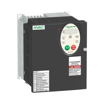
Schneider ATV212HU30N4 | variable speed drive ATV212 – 3kW – 480V – 3ph – EMC – IP21
Schneider ATV212HU30N4 | variable speed drive ATV212 – 3kW – 480V – 3ph – EMC – IP21
Original price was: EGP 70,032.48.EGP 38,517.86Current price is: EGP 38,517.86.
Description
Schneider ATV212HU30N4: The Ultimate Variable Speed Drive for Industrial Applications
Introduction
In today’s industrial landscape, the need for precise motor control and energy efficiency is paramount. it variable speed drive is a solution designed to meet these needs. But what exactly makes this drive stand out, and how can it benefit your operations?
What is Schneider ATV212HU30N4?
it is a versatile and efficient variable speed drive designed for controlling motor speeds in various applications. Known for its reliability and user-friendly interface, it is an essential tool for optimizing motor performance.
Technical Specifications
Understanding the technical specifications of it is crucial for its optimal use. Here are some key aspects:
- Power Rating: It has a power rating of 3 kW, suitable for medium-sized motors.
- Input and Output Voltage: Operates at an input voltage of 380-480V and provides a similar output voltage range.
- Frequency Range: Supports a frequency range of 0.5 to 200 Hz, offering flexibility in motor speed control.
Benefits of Using Schneider ATV212HU30N4
Why should you choose it for your motor control needs? Here are some compelling benefits:
- Enhanced Motor Control: Provides precise control over motor speeds, ensuring smooth operation.
- Energy Efficiency: Optimizes motor performance to reduce energy consumption and operational costs.
- Easy Integration: Designed for seamless integration with existing systems, minimizing installation hassle.
Installation and Setup
Installing the Schneider ATV212HU30N4 is straightforward but requires attention to detail:
Pre-installation Considerations
Ensure you have all necessary tools and understand the motor and system requirements where the drive will be installed.
Step-by-Step Installation Guide
- Turn off Power: Always start by shutting down the power to avoid any accidents.
- Mount the Device: Secure the drive in an accessible location.
- Connect Wires: Follow the wiring diagram to connect the device correctly.
- Power Up: Once everything is connected, turn the power back on and verify the installation.
Safety Precautions
Adhere to safety guidelines to prevent electrical hazards during installation.
User Interface and Connectivity
The user interface and connectivity options of the Schneider ATV212HU30N4 are designed for ease of use:
- Display and Control Features: It features a clear display and intuitive controls for easy operation.
- Connectivity Options: Ensures seamless integration with other industrial control systems and networks.
Applications of Schneider ATV212HU30N4
The versatility of the Schneider ATV212HU30N4 makes it suitable for various applications:
Industrial Usage
Ideal for manufacturing plants, automation systems, and conveyor belts, ensuring reliable motor control.
Commercial Usage
Perfect for HVAC systems, elevators, and other commercial motor-driven applications.
Specific Use Cases
Suitable for pumps, fans, and other critical processes requiring precise motor speed control.
Additional information
| brands | Schneider Electric |
|---|
Specifications
| Device short name | ATV212 |
|---|---|
| product destination | Asynchronous motors |
| Network number of phases | 3 phases |
| Motor power kW | 3 kW |
| Motor power hp | 4 hp |
| Supply voltage limits | 323…528 V |
| Supply frequency | 50...60 Hz - 5...5 % |
| Line current | 4.9 A at 480 V 6.2 A at 380 V |
| Range of product | Altivar 212 |
| product or component type | Variable speed drive |
| Product specific application | Pumps and fans in HVAC |
| Communication port protocol | METASYS N2 LonWorks Modbus BACnet APOGEE FLN |
| [Us] rated supply voltage | 380...480 V - 15...10 % |
| EMC filter | Class C2 EMC filter integrated |
| IP degree of protection | IP21 |
| Apparent power | 5.5 kVA at 380 V |
|---|---|
| Continuous output current | 7.2 A at 380 V 7.2 A at 460 V |
| Maximum transient current | 7.9 A for 60 s |
| Speed drive output frequency | 0.5…200 Hz |
| Speed range | 1…10 |
| Speed accuracy | +/- 10 % of nominal slip 0.2 Tn to Tn |
| Local signalling | 1 LED (red) for DC bus energized |
| Output voltage | <= power supply voltage |
| Isolation | Electrical between power and control |
| Type of cable | Without mounting kit: 1 wire(s)IEC cable at 45 °C, copper 90 °C / XLPE/EPR Without mounting kit: 1 wire(s)IEC cable at 45 °C, copper 70 °C / PVC With UL Type 1 kit: 3 wire(s)UL 508 cable at 40 °C, copper 75 °C / PVC |
| Electrical connection | VIA, VIB, FM, FLA, FLB, FLC, RY, RC, F, R, RES: terminal 2.5 mm² / AWG 14 L1/R, L2/S, L3/T: terminal 6 mm² / AWG 10 |
| Tightening torque | 1.3 N.m, 11.5 lb.in (L1/R, L2/S, L3/T) 0.6 N.m (VIA, VIB, FM, FLA, FLB, FLC, RY, RC, F, R, RES) |
| Supply | Internal supply for reference potentiometer (1 to 10 kOhm): 10.5 V DC +/- 5 %, <10 A, protection type: overload and short-circuit protection Internal supply: 24 V DC (21…27 V), <200 A, protection type: overload and short-circuit protection |
| Sampling duration | 2 ms +/- 0.5 ms F discrete 2 ms +/- 0.5 ms R discrete 2 ms +/- 0.5 ms RES discrete 3.5 ms +/- 0.5 ms VIA analog 22 ms +/- 0.5 ms VIB analog |
| Response time | FM 2 ms, tolerance +/- 0.5 ms for analog output(s) FLA, FLC 7 ms, tolerance +/- 0.5 ms for discrete output(s) FLB, FLC 7 ms, tolerance +/- 0.5 ms for discrete output(s) RY, RC 7 ms, tolerance +/- 0.5 ms for discrete output(s) |
| Accuracy | +/- 0.6 % (VIA) for a temperature variation 60 °C +/- 0.6 % (VIB) for a temperature variation 60 °C +/- 1 % (FM) for a temperature variation 60 °C |
| Linearity error | VIA: +/- 0.15 % of maximum value for input VIB: +/- 0.15 % of maximum value for input FM: +/- 0.2 % for output |
| Analogue output type | FM switch-configurable voltage 0...10 V DC, impedance: 7620 Ohm, resolution 10 bits FM switch-configurable current 0...20 mA, impedance: 970 Ohm, resolution 10 bits |
| Discrete output type | Configurable relay logic: (FLA, FLC) NO - 100000 cycles Configurable relay logic: (FLB, FLC) NC - 100000 cycles Configurable relay logic: (RY, RC) NO - 100000 cycles |
| Minimum switching current | 3 mA at 24 V DC for configurable relay logic |
| Maximum switching current | 5 A at 250 V AC on resistive load - cos phi = 1 - L/R = 0 ms (FL, R) 5 A at 30 V DC on resistive load - cos phi = 1 - L/R = 0 ms (FL, R) 2 A at 250 V AC on inductive load - cos phi = 0.4 - L/R = 7 ms (FL, R) 2 A at 30 V DC on inductive load - cos phi = 0.4 - L/R = 7 ms (FL, R) |
| Discrete input type | F programmable 24 V DC, with level 1 PLC, impedance: 4700 Ohm R programmable 24 V DC, with level 1 PLC, impedance: 4700 Ohm RES programmable 24 V DC, with level 1 PLC, impedance: 4700 Ohm |
| Discrete input logic | Positive logic (source) (F, R, RES), <= 5 V (state 0), >= 11 V (state 1) Negative logic (sink) (F, R, RES), >= 16 V (state 0), <= 10 V (state 1) |
| Dielectric strength | 3535 V DC between earth and power terminals 5092 V DC between control and power terminals |
| Insulation resistance | >= 1 mOhm 500 V DC for 1 minute |
| Frequency resolution | Display unit: 0.1 Hz Analog input: 0.024/50 Hz |
| communication service | Write multiple registers (16) 2 words maximum Read holding registers (03) 2 words maximum Time out setting from 0.1 to 100 s Read device identification (43) Monitoring inhibitable Write single register (06) |
| Option card | Communication card for LonWorks |
| Power dissipation in W | 137 W |
| Air flow | 47 m3/h |
| Functionality | Mid |
| Specific application | HVAC |
| Variable speed drive application selection | Building - HVAC compressor for scroll Building - HVAC fan Building - HVAC pump |
| Motor power range AC-3 | 2.2…3 kW at 380…440 V 3 phases 2.2…3 kW at 480…500 V 3 phases |
| Motor starter type | Variable speed drive |
| Discrete output number | 2 |
| Analogue input number | 2 |
| Analogue input type | VIA switch-configurable voltage: 0...10 V DC 24 V max, impedance: 30000 Ohm, resolution 10 bits VIB configurable voltage: 0...10 V DC 24 V max, impedance: 30000 Ohm, resolution 10 bits VIB configurable PTC probe: 0...6 probes, impedance: 1500 Ohm VIA switch-configurable current: 0...20 mA, impedance: 250 Ohm, resolution 10 bits |
| Analogue output number | 1 |
| Physical interface | 2-wire RS 485 |
| Connector type | 1 open style 1 RJ45 |
| Transmission rate | 9600 bps or 19200 bps |
| Transmission frame | RTU |
| Number of addresses | 1…247 |
| Data format | 8 bits, 1 stop, odd even or no configurable parity |
| Type of polarization | No impedance |
| Asynchronous motor control profile | Voltage/frequency ratio, 2 points Voltage/frequency ratio, 5 points Voltage/frequency ratio, automatic IR compensation (U/f + automatic Uo) Voltage/frequency ratio - Energy Saving, quadratic U/f Flux vector control without sensor, standard |
| Torque accuracy | +/- 15 % |
| Transient overtorque | 120 % of nominal motor torque +/- 10 % for 60 s |
| Acceleration and deceleration ramps | Automatic based on the load Linear adjustable separately from 0.01 to 3200 s |
| Motor slip compensation | Adjustable Automatic whatever the load Not available in voltage/frequency ratio motor control |
| Switching frequency | 6...16 kHz adjustable 12...16 kHz with derating factor |
| Nominal switching frequency | 12 kHz |
| Braking to standstill | By DC injection |
| Network frequency | 47.5...63 Hz |
| Prospective line Isc | 5 kA |
| Protection type | Overheating protection: drive Thermal power stage: drive Short-circuit between motor phases: drive Input phase breaks: drive Overcurrent between output phases and earth: drive Overvoltages on the DC bus: drive Break on the control circuit: drive Against exceeding limit speed: drive Line supply overvoltage and undervoltage: drive Line supply undervoltage: drive Against input phase loss: drive Thermal protection: motor Motor phase break: motor With PTC probes: motor |
| Width | 142 mm |
| Height | 184 mm |
| Depth | 150 mm |
| net weight | 3.35 kg |
| Pollution degree | 3 conforming to IEC 61800-5-1 |
|---|---|
| IP degree of protection | IP20 on upper part without blanking plate on cover conforming to IEC 61800-5-1 IP20 on upper part without blanking plate on cover conforming to IEC 60529 IP21 conforming to IEC 61800-5-1 IP21 conforming to IEC 60529 IP41 on upper part conforming to IEC 61800-5-1 IP41 on upper part conforming to IEC 60529 |
| Vibration resistance | 1.5 mm (f= 3…13 Hz) conforming to IEC 60068-2-6 1 gn (f= 13…200 Hz) conforming to EN/IEC 60068-2-8 |
| Shock resistance | 15 gn for 11 ms conforming to IEC 60068-2-27 |
| Environmental characteristic | Classes 3C1 conforming to IEC 60721-3-3 Classes 3S2 conforming to IEC 60721-3-3 |
| Noise level | 51 dB conforming to 86/188/EEC |
| Operating altitude | 1000...3000 m limited to 2000 m for the Corner Grounded distribution network with current derating 1 % per 100 m <= 1000 m without derating |
| Relative humidity | 5…95 % without condensation conforming to IEC 60068-2-3 5…95 % without dripping water conforming to IEC 60068-2-3 |
| Ambient air temperature for operation | -10…40 °C (without derating) 40…50 °C (with derating factor) |
| Operating position | Vertical +/- 10 degree |
| Product certifications | C-Tick NOM 117 UL CSA |
| marking | CE |
| Standards | IEC 61800-3 environments 1 category C3 IEC 61800-3 environments 1 category C3 IEC 61800-3 environments 2 category C3 IEC 61800-3 category C2 IEC 61800-3 environments 2 category C2 IEC 61800-3 environments 2 category C1 EN 61800-3 category C3 IEC 61800-3 category C3 IEC 61800-3 environments 1 category C2 IEC 61800-3 IEC 61800-5-1 EN 55011 class A group 1 IEC 61800-3 environments 2 category C1 IEC 61800-3 IEC 61800-3 category C2 IEC 61800-3 environments 2 category C3 IEC 61800-5-1 UL Type 1 IEC 61800-3 environments 1 category C2 IEC 61800-3 environments 2 category C2 IEC 61800-3 environments 1 category C1 IEC 61800-3 environments 1 category C1 |
| Assembly style | With heat sink |
| Electromagnetic compatibility | Electrostatic discharge immunity test level 3 conforming to IEC 61000-4-2 Radiated radio-frequency electromagnetic field immunity test level 3 conforming to IEC 61000-4-3 Electrical fast transient/burst immunity test level 4 conforming to IEC 61000-4-4 1.2/50 µs - 8/20 µs surge immunity test level 3 conforming to IEC 61000-4-5 Conducted radio-frequency immunity test level 3 conforming to IEC 61000-4-6 Voltage dips and interruptions immunity test conforming to IEC 61000-4-11 |
| Regulation loop | Adjustable PI regulator |
| Ambient air temperature for storage | -25…70 °C |
| Unit Type of Package 1 | PCE |
|---|---|
| Number of Units in Package 1 | 1 |
| Package 1 Height | 21.700 cm |
| Package 1 Width | 21.500 cm |
| Package 1 Length | 21.500 cm |
| Package 1 Weight | 3.092 kg |
| Unit Type of Package 2 | S06 |
| Number of Units in Package 2 | 12 |
| Package 2 Height | 75.000 cm |
| Package 2 Width | 60.000 cm |
| Package 2 Length | 80.000 cm |
| Package 2 Weight | 49.444 kg |
| Warranty | 18 months |
|---|


Reviews
There are no reviews yet.