
No products in the cart.
new

Altivar Solar, Industrial Automation and Control, Low Voltage AC Industry -Specific Drives, Variable Speed Drives and Soft Starters
Schneider ATV320U55M3C412 | Variable speed drive, Altivar Solar, 5.5kW, 200 to 240V, 3 phases, compact
Schneider ATV320U55M3C412 | Variable speed drive, Altivar Solar, 5.5kW, 200 to 240V, 3 phases, compact
Designed for Solar and Pumping applications
Reduce your OPEX
Easy scalability of your Automation system
Future-ready solution for Industry 4.0
Improve power quality of your system with a low investment
Description
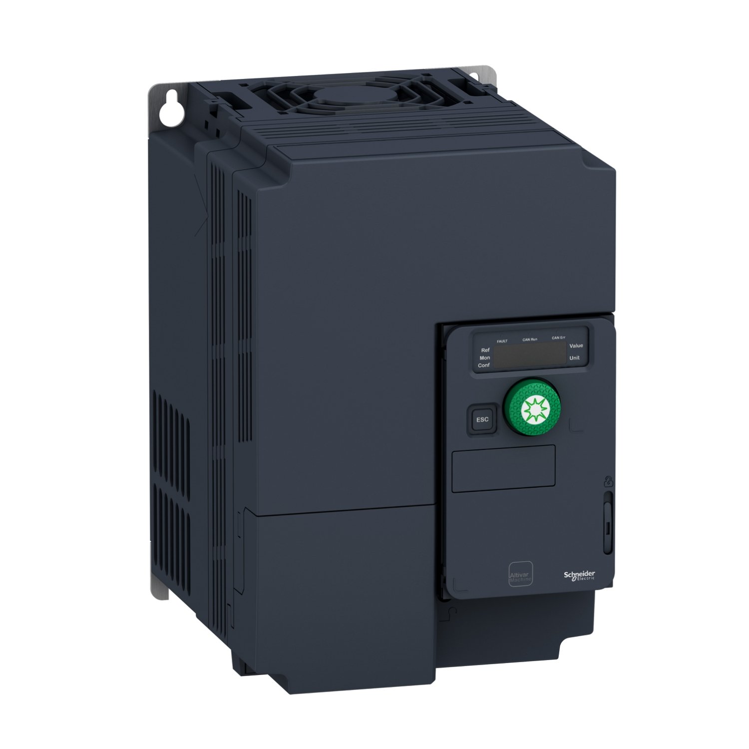
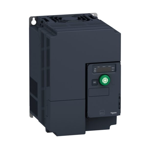
Schneider ATV320U55M3C412 | Variable speed drive, Altivar Solar, 5.5kW, 200 to 240V, 3 phases, compact

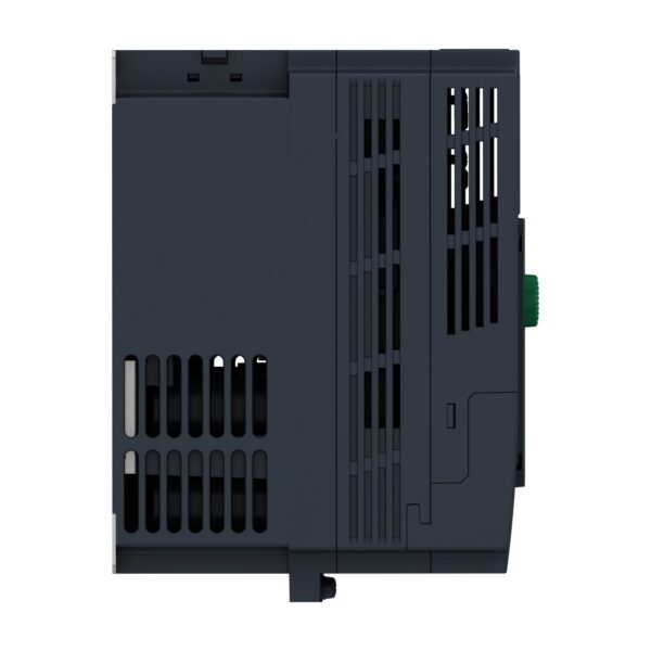
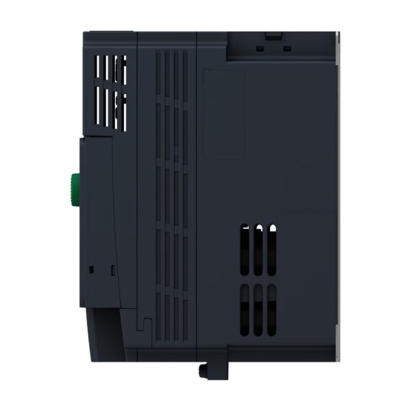
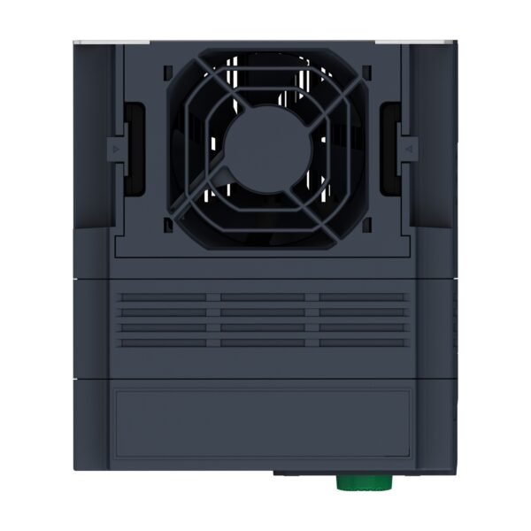
The Schneider Altivar ATV320U55M3C412 is a compact variable speed drive (VSD) from the Altivar Solar range, designed for efficient operation of solar water pumping systems. It is a 5.5 kW drive that operates on a three-phase voltage of 200 to 240V.
Key Features and Benefits
This VSD is built to maximize the performance of a solar-powered pump. Its main feature is Maximum Power Point Tracking (MPPT), which continuously adjusts the motor’s speed to extract the highest possible power from the solar panels. This ensures that the pump operates at peak efficiency, delivering maximum water output even under varying sunlight conditions.
The drive has a space-saving, book-style form factor and includes an integrated C2 EMC filter. It is equipped with safety functions, including Safe Torque Off (STO), which prevents accidental motor startup. It also offers specific protections for pumping, such as dry-run protection, which automatically shuts off the pump when the water source runs dry, preventing damage. The drive’s dual-supply capability allows it to operate from either a solar array or a conventional AC grid, ensuring reliable operation.
Primary Applications
The Schneider Altivar ATV320U55M3C412 is a reliable solution for various medium-scale solar pumping needs, particularly in remote or off-grid areas. Its primary applications include:
Agricultural Irrigation: Providing water for farms and greenhouses.
Residential and Community Water Supply: Supplying water to homes and villages in off-grid locations.
Water Transfer: Pumping water for filling large tanks and reservoirs.
Livestock Watering: Ensuring a consistent water source for animals in pastures.
Additional information
| brands | Schneider Electric |
|---|
Specifications
| Range of product | Altivar Solar |
|---|---|
| Product or component type | Variable speed drive |
| Product specific application | Pumping applications |
| Variant | Standard version |
| Format of the drive | Compact |
| Mounting mode | Wall mount |
| Communication port protocol | Modbus serial CANopen |
| Option card | Communication module, Ethernet IP/Modbus TCP |
| [Us] rated supply voltage | 200...240 V - 15...10 % |
| nominal output current | 27.5 A |
| Motor power kW | 5.5 kW for heavy duty |
| EMC filter | Without EMC filter |
| IP degree of protection | IP20 |
| Discrete input number | 7 |
|---|---|
| Discrete input type | STO safe torque off, 24 V DC, impedance: 1.5 kOhm DI1...DI6 logic inputs, 24 V DC (30 V) DI5 programmable as pulse input: 0…30 kHz, 24 V DC (30 V) |
| Discrete input logic | Positive logic (source) Negative logic (sink) |
| Discrete output number | 3 |
| Discrete output type | Open collector DQ+ 0…1 kHz 30 V DC 100 mA Open collector DQ- 0…1 kHz 30 V DC 100 mA |
| Analogue input number | 3 |
| Analogue input type | AI1 voltage: 0...10 V DC, impedance: 30 kOhm, resolution 10 bits AI2 bipolar differential voltage: +/- 10 V DC, impedance: 30 kOhm, resolution 10 bits AI3 current: 0...20 mA (or 4-20 mA, x-20 mA, 20-x mA or other patterns by configuration), impedance: 250 Ohm, resolution 10 bits |
| Analogue output number | 1 |
| Analogue output type | Software-configurable current AQ1: 0...20 mA impedance 800 Ohm, resolution 10 bits Software-configurable voltage AQ1: 0...10 V DC impedance 470 Ohm, resolution 10 bits |
| Relay output number | 2 |
| Relay output type | Configurable relay logic R1A 1 NO electrical durability 100000 cycles Configurable relay logic R1B 1 NC electrical durability 100000 cycles Configurable relay logic R1C Configurable relay logic R2A 1 NO electrical durability 100000 cycles Configurable relay logic R2C |
| Maximum switching current | Relay output R1A, R1B, R1C on resistive load, cos phi = 1: 3 A at 250 V AC Relay output R1A, R1B, R1C on resistive load, cos phi = 1: 3 A at 30 V DC Relay output R1A, R1B, R1C, R2A, R2C on inductive load, cos phi = 0.4 and L/R = 7 ms: 2 A at 250 V AC Relay output R1A, R1B, R1C, R2A, R2C on inductive load, cos phi = 0.4 and L/R = 7 ms: 2 A at 30 V DC Relay output R2A, R2C on resistive load, cos phi = 1: 5 A at 250 V AC Relay output R2A, R2C on resistive load, cos phi = 1: 5 A at 30 V DC |
| Minimum switching current | Relay output R1A, R1B, R1C, R2A, R2C: 5 mA at 24 V DC |
| Method of access | Slave CANopen |
| Number of addresses | 1…247 1…127 |
| Data format | 8 bits, configurable odd, even or no parity |
| Type of polarization | No impedance |
| 4 quadrant operation possible | True |
| Asynchronous motor control profile | Voltage/frequency ratio, 5 points Flux vector control without sensor, standard Voltage/frequency ratio - Energy Saving, quadratic U/f Flux vector control without sensor - Energy Saving Voltage/frequency ratio, 2 points |
| Synchronous motor control profile | Vector control without sensor |
| Maximum output frequency | 0.599 kHz |
| Acceleration and deceleration ramps | Linear U S CUS Ramp switching Acceleration/deceleration ramp adaptation Acceleration/deceleration automatic stop with DC injection Automatic adaptation of ramp if braking capacity exceeded, by using resistor Linear adjustable separately from 0.01 to 6000 s |
| Motor slip compensation | Automatic whatever the load Adjustable 0...300 % Not available in voltage/frequency ratio (2 or 5 points) |
| Switching frequency | 2...16 kHz adjustable 4...16 kHz with derating factor |
| Nominal switching frequency | 4 kHz |
| Braking to standstill | By DC injection |
| Brake chopper integrated | True |
| Line current | 35.4 A at 200 V (heavy duty) 29.8 A at 240 V (heavy duty) |
| Maximum input current | 35.4 A |
| Maximum output voltage | 240 V |
| Apparent power | 12.4 kVA at 240 V (heavy duty) |
| Maximum transient current | 41.3 A during 60 s |
| Short-circuit protection | thermal protection |
| Network frequency | 50...60 Hz |
| Relative symmetric network frequency tolerance | 5 % |
| Prospective line Isc | 22 kA |
| Base load current at high overload | 27.5 A |
| Power dissipation in W | Fan: 242.0 W at 200 V, switching frequency 4 kHz |
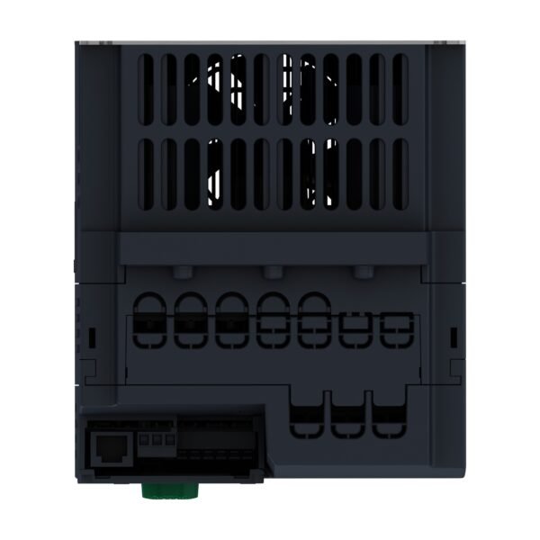
| Electrical connection | Screw terminal, clamping capacity: 0.5...1.5 mm² for analog input Screw terminal for analog output Screw terminal |
| With safety function Safely Limited Speed (SLS) | True |
| With safety function Safe brake management (SBC/SBT) | False |
| With safety function Safe Operating Stop (SOS) | False |
| With safety function Safe Position (SP) | False |
| With safety function Safe programmable logic | False |
| With safety function Safe Speed Monitor (SSM) | False |
| With safety function Safe Stop 1 (SS1) | True |
| With sft fct Safe Stop 2 (SS2) | False |
| With safety function Safe torque off (STO) | True |
| With safety function Safely Limited Position (SLP) | False |
| With safety function Safe Direction (SDI) | False |
| Protection type | Input phase breaks: drive Overcurrent between output phases and earth: drive Overheating protection: drive Short-circuit between motor phases: drive Thermal protection: drive |
| Width | 150 mm |
| Height | 232.0 mm |
| Depth | 178.0 mm |
| Net weight | 3.5 kg |
| Power factor | 0.552 at 230 V |
| Braking torque | 170 % with braking resistor |
| Local signalling | 1 LED (red) for drive fault 1 LED (red) for CANopen error 1 LED (green) for CANopen run |
| Transient overtorque | 170…200 % of nominal motor torque |
| Operating position | Vertical +/- 10 degree |
|---|---|
| Product certifications | CE UR UKCA RCM |
| Marking | CE UR UKCA RCM |
| Standards | IEC 61800-5-1 |
| Assembly style | With heat sink |
| Electromagnetic compatibility | Electrostatic discharge immunity test level 3 conforming to IEC 61000-4-2 Radiated radio-frequency electromagnetic field immunity test level 3 conforming to IEC 61000-4-3 Electrical fast transient/burst immunity test level 4 conforming to IEC 61000-4-4 1.2/50 µs - 8/20 µs surge immunity test level 3 conforming to IEC 61000-4-5 Conducted radio-frequency immunity test level 3 conforming to IEC 61000-4-6 Voltage dips and interruptions immunity test conforming to IEC 61000-4-11 |
| Environmental class (during operation) | Class 3C3 according to IEC 60721-3-3 Class 3S2 according to IEC 60721-3-3 |
| Maximum acceleration under shock impact (during operation) | 150 m/s² at 11 ms |
| Maximum acceleration under vibrational stress (during operation) | 10 m/s² at 13...200 Hz |
| Maximum deflection under vibratory load (during operation) | 1.5 mm at 2...13 Hz |
| Permitted relative humidity (during operation) | Class 3K5 according to EN 60721-3 |
| Volume of cooling air | 60 m3/h |
| Overvoltage category | II |
| Regulation loop | Adjustable PID regulator |
| Speed accuracy | +/- 10 % of nominal slip 0.2 Tn to Tn |
| Noise level | 54 dB |
| Pollution degree | 2 |
| Ambient air transport temperature | -25…70 °C |
| Ambient air temperature for operation | -10…50 °C without derating 50…60 °C with derating factor |
| Ambient air temperature for storage | -25…70 °C |
| Operating altitude | 1000...2000 m with current derating 1 % per 100 m <= 1000 m without derating |
| Unit Type of Package 1 | PCE |
|---|---|
| Number of Units in Package 1 | 1 |
| Package 1 Height | 19.5 cm |
| Package 1 Width | 22 cm |
| Package 1 Length | 33 cm |
| Package 1 Weight | 4.185 kg |
| Unit Type of Package 2 | S06 |
| Number of Units in Package 2 | 10 |
| Package 2 Height | 75 cm |
| Package 2 Width | 60 cm |
| Package 2 Length | 80 cm |
| Package 2 Weight | 54.85 kg |


Reviews
There are no reviews yet.