
No products in the cart.
-46%On Sale
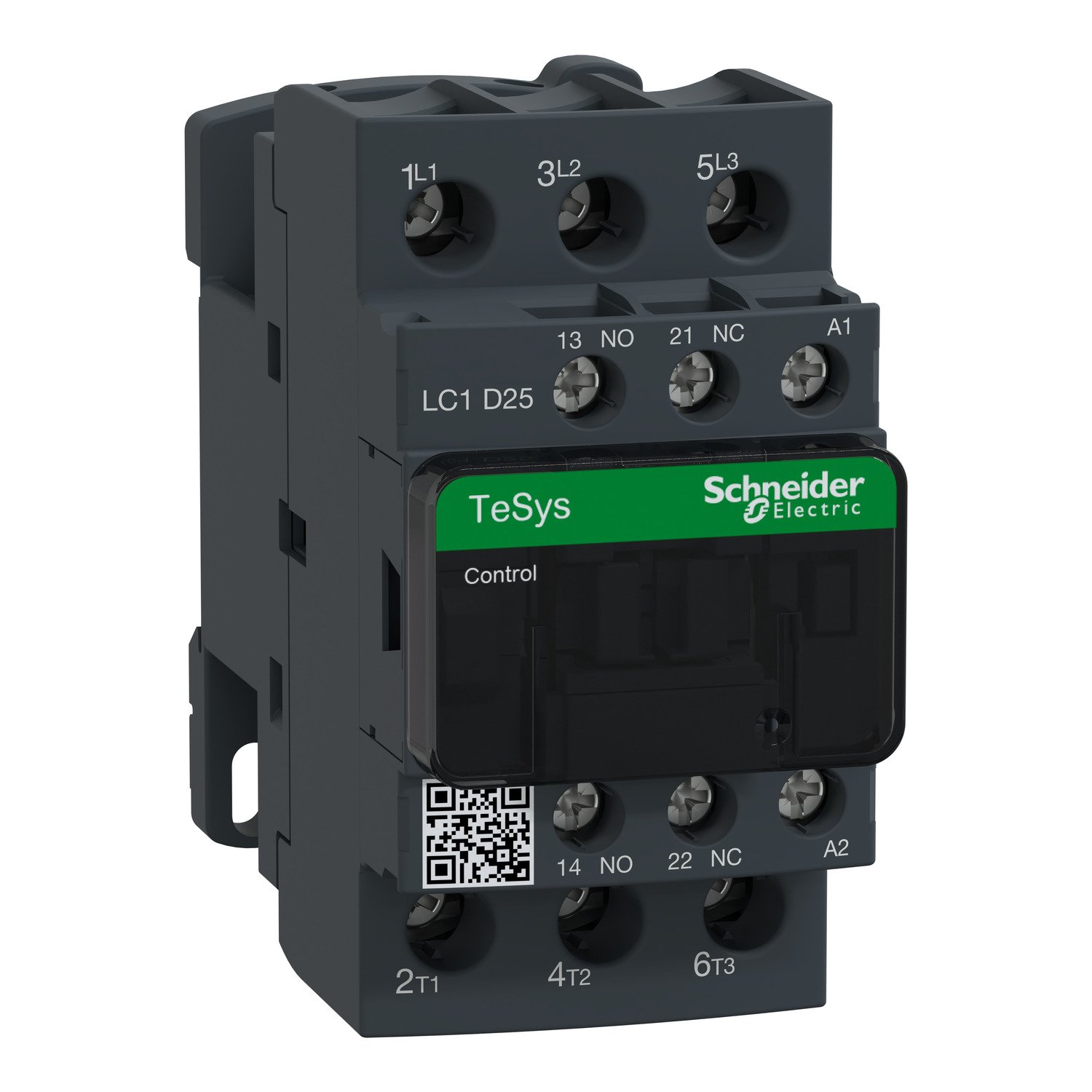
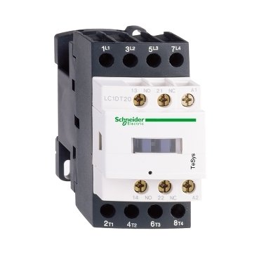
Schneider LC1D25M7 | TeSys D contactor – 3P(3 NO) – AC-3 – <= 440 V 25 A – 220 V AC coil
Schneider LC1D25M7
Original price was: EGP 5,244.65.EGP 2,837.60Current price is: EGP 2,837.60.
Description
Schneider LC1D25M7
Introduction
In the world of electrical control systems, it stands out as a crucial component. This guide will explore its significance, features, applications, and much more, offering a thorough understanding of why this device is essential in various electrical setups.
Overview of Schneider Electric
Schneider Electric, a renowned leader in energy management and automation, has a long history of innovation and excellence. With roots dating back to the 19th century, the company is dedicated to providing efficient, reliable, and sustainable solutions for a wide range of industries.
Understanding the Schneider LC1D25M7
Technical Specifications
it is known for its robust technical specifications. Key specs include:
- Voltage Rating: Up to 690V
- Current Rating: 25A
- Operating Frequency: 50/60 Hz
- Contact Configuration: 3PST (3 Pole Single Throw)
Key Features
- High Durability: Designed to withstand harsh industrial environments.
- Compact Design: Easy to integrate into various systems.
- Energy Efficiency: Reduces energy consumption, making it eco-friendly.
- Advanced Safety Features: Includes protections against overload and short circuits.
Applications of Schneider LC1D25M7
Residential Uses
In homes, it ensures the smooth operation of electrical systems, enhancing safety and efficiency. It’s ideal for managing circuits and household appliances.
Commercial Uses
For businesses, this contactor supports various electrical needs, from lighting systems to HVAC units. It boosts operational efficiency and reduces energy costs, making it a valuable asset for commercial properties.
Industrial Uses
Industries depend on reliable electrical systems to operate heavy machinery and complex processes. it offers the robustness and reliability needed for such demanding applications.
Installation Process
Step-by-Step Guide
- Preparation: Gather all necessary tools and components.
- Safety First: Ensure the power is disconnected before starting.
- Mounting: Secure the contactor in the designated location.
- Wiring: Connect the wires as per the installation manual.
- Testing: Reconnect power and test the system for proper functionality.
Safety Precautions
- Always adhere to the manufacturer’s guidelines.
- Use protective gear such as gloves and safety glasses.
- Verify all connections to avoid electrical hazards.
Benefits of Using Schneider LC1D25M7
Efficiency
it is engineered to maximize efficiency, reducing energy wastage and enhancing overall system performance.
Reliability
Known for its sturdy construction, this contactor provides exceptional reliability, ensuring your electrical systems remain operational.
Cost-Effectiveness
By optimizing energy use and minimizing the need for frequent replacements, it proves to be a cost-effective solution over time.
Comparing Schneider LC1D25M7 with Other Models
Schneider Models
Within the Schneider Electric range, it is distinguished by its advanced features and superior performance relative to other models.
Competitor Models
When compared to competitor models, it often excels in terms of reliability, efficiency, and comprehensive safety features.
Maintenance Tips
Regular Checks
Regular inspections ensure that the contactor is functioning correctly. Look for signs of wear and tear and address them promptly to avoid major issues.
Troubleshooting Common Issues
Common problems may include tripping circuits or unusual noises. Refer to the user manual for troubleshooting tips or contact Schneider Electric support for help.
Energy Efficiency
How it Conserves Energy
it is designed to optimize energy use, significantly reducing your energy footprint.
Impact on Utility Bills
By conserving energy, this contactor can help lower your utility bills, making it a wise investment for both residential and commercial use.
Additional information
| brands | Schneider Electric |
|---|
Specifications
| Range of produc | TeSys Deca |
|---|---|
| Product or component type | Contactor |
| Device short name | LC1D |
| contactor application | Motor control Resistive load |
| utilisation category | AC-1 AC-3 AC-4 AC-3e |
| Poles description | 3P |
| [Ue] rated operational voltage | Power circuit: <= 690 V AC 25...400 Hz Power circuit: <= 300 V DC |
| [Ie] rated operational current | 25 A (at <60 °C) at <= 440 V AC AC-3 for power circuit 40 A (at <60 °C) at <= 440 V AC AC-1 for power circuit 25 A (at <60 °C) at <= 440 V AC AC-3e for power circuit |
| [Uc] control circuit voltage | 220 V AC 50/60 Hz |
| Motor power kW | 5.5 kW at 220...230 V AC 50/60 Hz (AC-3) 11 kW at 380...400 V AC 50/60 Hz (AC-3) 11 kW at 415...440 V AC 50/60 Hz (AC-3) 15 kW at 500 V AC 50/60 Hz (AC-3) 15 kW at 660...690 V AC 50/60 Hz (AC-3) 5.5 kW at 400 V AC 50/60 Hz (AC-4) 5.5 kW at 220...230 V AC 50/60 Hz (AC-3e) 11 kW at 380...400 V AC 50/60 Hz (AC-3e) 11 kW at 415...440 V AC 50/60 Hz (AC-3e) 15 kW at 500 V AC 50/60 Hz (AC-3e) 15 kW at 660...690 V AC 50/60 Hz (AC-3e) |
|---|---|
| Motor power hp | 3 hp at 230/240 V AC 50/60 Hz for 1 phase motors 2 hp at 115 V AC 50/60 Hz for 1 phase motors 7.5 hp at 230/240 V AC 50/60 Hz for 3 phases motors 15 hp at 460/480 V AC 50/60 Hz for 3 phases motors 20 hp at 575/600 V AC 50/60 Hz for 3 phases motors 7.5 hp at 200/208 V AC 50/60 Hz for 3 phases motors |
| Compatibility code | LC1D |
| Pole contact composition | 3 NO |
| Contact compatibility | M2 |
| Protective cover | With |
| [Ith] conventional free air thermal current | 10 A (at 60 °C) for signalling circuit 40 A (at 60 °C) for power circuit |
| Irms rated making capacity | 140 A AC for signalling circuit conforming to IEC 60947-5-1 250 A DC for signalling circuit conforming to IEC 60947-5-1 450 A at 440 V for power circuit conforming to IEC 60947 |
| Rated breaking capacity | 450 A at 440 V for power circuit conforming to IEC 60947 |
| [Icw] rated short-time withstand current | 240 A 40 °C - 10 s for power circuit 380 A 40 °C - 1 s for power circuit 50 A 40 °C - 10 min for power circuit 120 A 40 °C - 1 min for power circuit 100 A - 1 s for signalling circuit 120 A - 500 ms for signalling circuit 140 A - 100 ms for signalling circuit |
| Associated fuse rating | 10 A gG for signalling circuit conforming to IEC 60947-5-1 63 A gG at <= 690 V coordination type 1 for power circuit 40 A gG at <= 690 V coordination type 2 for power circuit |
| Average impedance | 2 mOhm - Ith 40 A 50 Hz for power circuit |
| Power dissipation per pole | 3.2 W AC-1 1.25 W AC-3 1.25 W AC-3e |
| [Ui] rated insulation voltage | Power circuit: 690 V conforming to IEC 60947-4-1 Power circuit: 600 V CSA certified Power circuit: 600 V UL certified Signalling circuit: 690 V conforming to IEC 60947-1 Signalling circuit: 600 V CSA certified Signalling circuit: 600 V UL certified |
| Overvoltage category | III |
| Pollution degree | 3 |
| [Uimp] rated impulse withstand voltage | 6 kV conforming to IEC 60947 |
| Safety reliability level | B10d = 1369863 cycles contactor with nominal load conforming to EN/ISO 13849-1 B10d = 20000000 cycles contactor with mechanical load conforming to EN/ISO 13849-1 |
| Mechanical durability | 15 Mcycles |
| Electrical durability | 1.65 Mcycles 25 A AC-3 at Ue <= 440 V 1.4 Mcycles 40 A AC-1 at Ue <= 440 V 1.65 Mcycles 25 A AC-3e at Ue <= 440 V |
| Control circuit type | AC at 50/60 Hz standard |
| Coil technology | Without built-in suppressor module |
| Control circuit voltage limits | 0.3...0.6 Uc (-40…70 °C):drop-out AC 50/60 Hz 0.8...1.1 Uc (-40…60 °C):operational AC 50 Hz 0.85...1.1 Uc (-40…60 °C):operational AC 60 Hz 1...1.1 Uc (60…70 °C):operational AC 50/60 Hz |
| Inrush power in VA | 70 VA 60 Hz cos phi 0.75 (at 20 °C) 70 VA 50 Hz cos phi 0.75 (at 20 °C) |
| Hold-in power consumption in VA | 7.5 VA 60 Hz cos phi 0.3 (at 20 °C) 7 VA 50 Hz cos phi 0.3 (at 20 °C) |
| Heat dissipation | 2…3 W at 50/60 Hz |
| Operating time | 12...22 ms closing 4...19 ms opening |
| Maximum operating rate | 3600 cyc/h 60 °C |
| Connections - terminals | Control circuit: screw clamp terminals 1 1…4 mm² - cable stiffness: flexible without cable end Control circuit: screw clamp terminals 2 1…4 mm² - cable stiffness: flexible without cable end Control circuit: screw clamp terminals 1 1…4 mm² - cable stiffness: flexible with cable end Control circuit: screw clamp terminals 2 1…2.5 mm² - cable stiffness: flexible with cable end Control circuit: screw clamp terminals 1 1…4 mm² - cable stiffness: solid without cable end Control circuit: screw clamp terminals 2 1…4 mm² - cable stiffness: solid without cable end Power circuit: screw clamp terminals 1 2.5…10 mm² - cable stiffness: flexible without cable end Power circuit: screw clamp terminals 2 2.5…10 mm² - cable stiffness: flexible without cable end Power circuit: screw clamp terminals 1 1…10 mm² - cable stiffness: flexible with cable end Power circuit: screw clamp terminals 2 1.5…6 mm² - cable stiffness: flexible with cable end Power circuit: screw clamp terminals 1 1.5…10 mm² - cable stiffness: solid without cable end Power circuit: screw clamp terminals 2 2.5…10 mm² - cable stiffness: solid without cable end |
| Tightening torque | Control circuit: 1.7 N.m - on screw clamp terminals - with screwdriver flat Ø 6 mm Control circuit: 1.7 N.m - on screw clamp terminals - with screwdriver Philips No 2 Power circuit: 2.5 N.m - on screw clamp terminals - with screwdriver flat Ø 6 mm Power circuit: 2.5 N.m - on screw clamp terminals - with screwdriver Philips No 2 Control circuit: 1.7 N.m - on screw clamp terminals - with screwdriver pozidriv No 2 Power circuit: 2.5 N.m - on screw clamp terminals - with screwdriver pozidriv No 2 |
| Auxiliary contact composition | 1 NO + 1 NC |
| Auxiliary contacts type | Type mechanically linked 1 NO + 1 NC conforming to IEC 60947-5-1 type mirror contact 1 NC conforming to IEC 60947-4-1 |
| Signalling circuit frequency | 25...400 Hz |
| Minimum switching voltage | 17 V for signalling circuit |
| Minimum switching current | 5 mA for signalling circuit |
| Insulation resistance | > 10 MOhm for signalling circuit |
| Non-overlap time | 1.5 ms on de-energisation between NC and NO contact 1.5 ms on energisation between NC and NO contact |
| mounting support | Plate Rail |
| Standards | CSA C22.2 No 14 EN 60947-4-1 EN 60947-5-1 IEC 60947-4-1 IEC 60947-5-1 UL 508 IEC 60335-1 |
|---|---|
| product certifications | BV GL LROS (Lloyds register of shipping) GOST UL DNV CCC CSA RINA UKCA |
| IP degree of protection | IP20 front face conforming to IEC 60529 |
| Protective treatment | TH conforming to IEC 60068-2-30 |
| Climatic withstand | Conforming to IACS E10 exposure to damp heat conforming to IEC 60947-1 Annex Q category D exposure to damp heat |
| Permissible ambient air temperature around the device | -40…60 °C 60…70 °C with derating |
| Operating altitude | 0...3000 m |
| Fire resistance | 850 °C conforming to IEC 60695-2-1 |
| Flame retardance | V1 conforming to UL 94 |
| Mechanical robustness | Vibrations contactor open (2 Gn, 5...300 Hz) Vibrations contactor closed (4 Gn, 5...300 Hz) Shocks contactor closed (15 Gn for 11 ms) Shocks contactor open (8 Gn for 11 ms) |
| height | 85 mm |
| Width | 45 mm |
| Depth | 92 mm |
| Net weight | 0.37 kg |
| Unit Type of Package 1 | PCE |
|---|---|
| Number of Units in Package 1 | 1 |
| Package 1 Height | 5.000 cm |
| Package 1 Width | 9.300 cm |
| Package 1 Length | 11.400 cm |
| Package 1 Weight | 413.000 g |
| Unit Type of Package 2 | S02 |
| Number of Units in Package 2 | 20 |
| Package 2 Height | 15.000 cm |
| Package 2 Width | 30.000 cm |
| Package 2 Length | 40.000 cm |
| Package 2 Weight | 8.440 kg |
| Unit Type of Package 3 | P06 |
| Number of Units in Package 3 | 320 |
| Package 3 Height | 75.000 cm |
| Package 3 Width | 60.000 cm |
| Package 3 Length | 80.000 cm |
| Package 3 Weight | 143.000 kg |
| Warranty | 18 months |
|---|


Reviews
There are no reviews yet.