
No products in the cart.
-46%On Sale
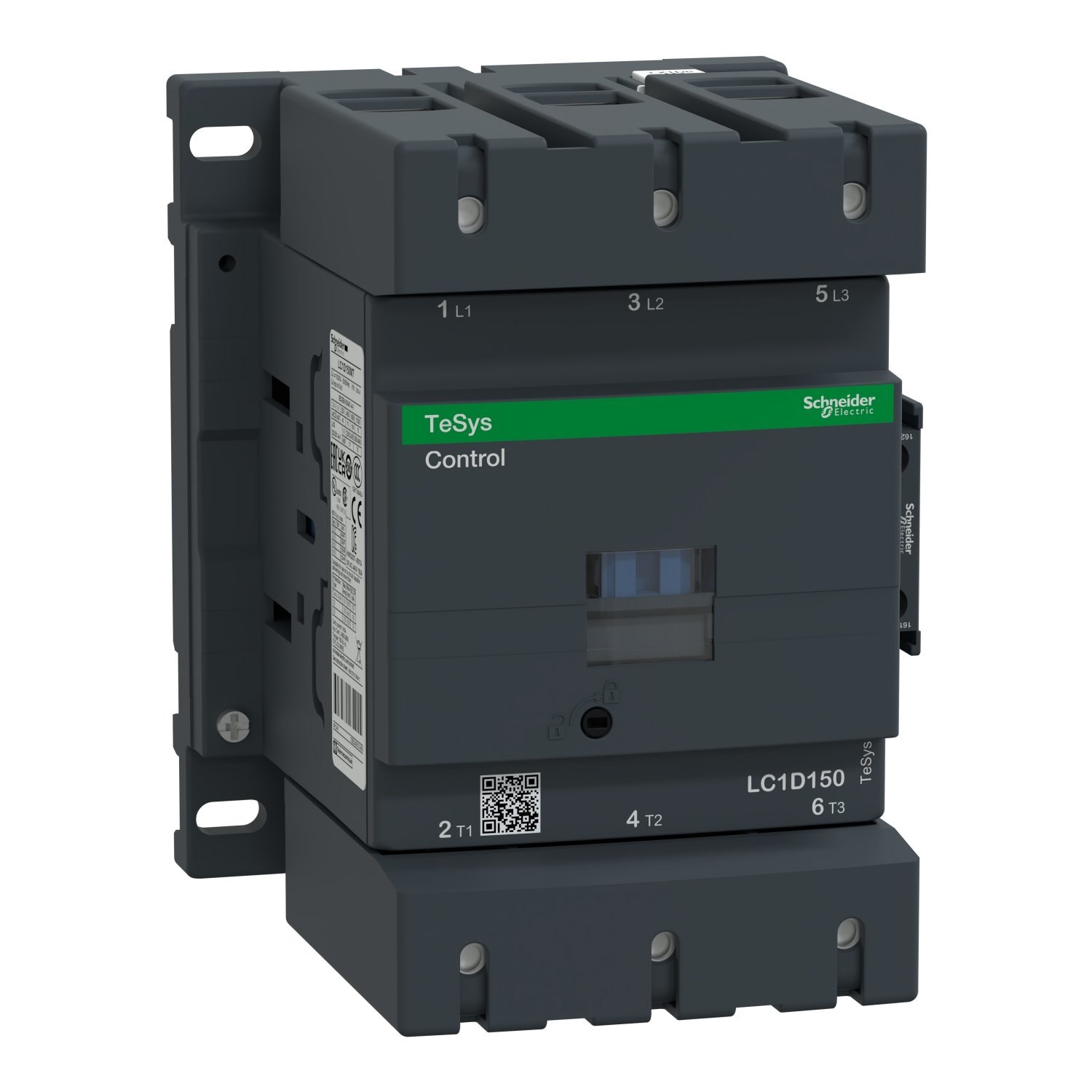
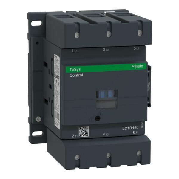
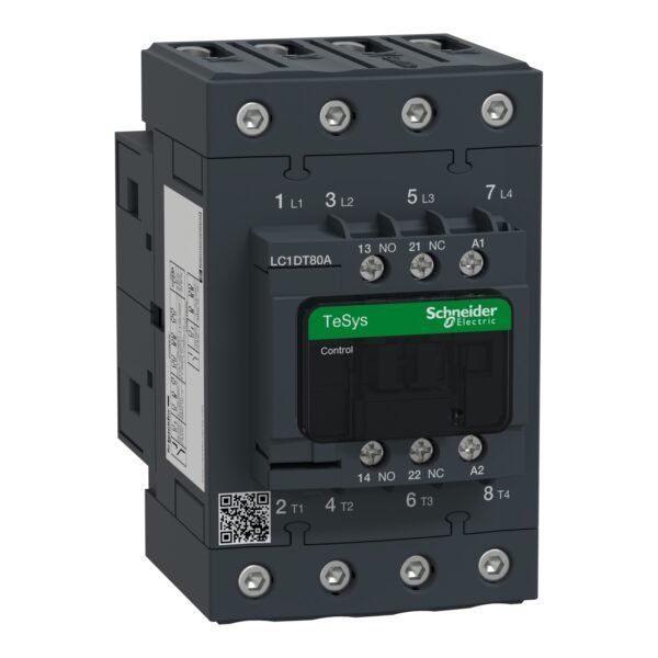
Schneider LC1D150Q7 Contactor | TeSys D- 3P(3 NO) – AC-3 – <= 440 V 150 A – 380 V AC 50/60 Hz coil
Schneider LC1D150Q7 Contactor
Original price was: EGP 38,517.18.EGP 20,839.80Current price is: EGP 20,839.80.
Description
Schneider LC1D150Q7 Contactor: A Comprehensive Guide
When it comes to managing electrical loads efficiently and safely, having the right contactor is paramount. In this guide, we’ll delve into the specifics of the Schneider LC1D150Q7 Contactor, exploring its features, applications, installation process, maintenance tips, safety precautions, and more.
Understanding Contactor Basics
What is a contactor?
A contactor is an electrical device designed to control the flow of electricity in a circuit. It consists of a set of contacts that open and close to allow or interrupt the flow of current. Contactors are commonly used in industrial and commercial applications to switch power circuits on and off.
Importance of contactors in electrical systems
Contactors play a crucial role in protecting electrical equipment from damage due to overload or short circuits. They help ensure the smooth operation of machinery and prevent potential hazards, making them indispensable components in various electrical systems.
Features of Schneider LC1D150Q7 Contactor
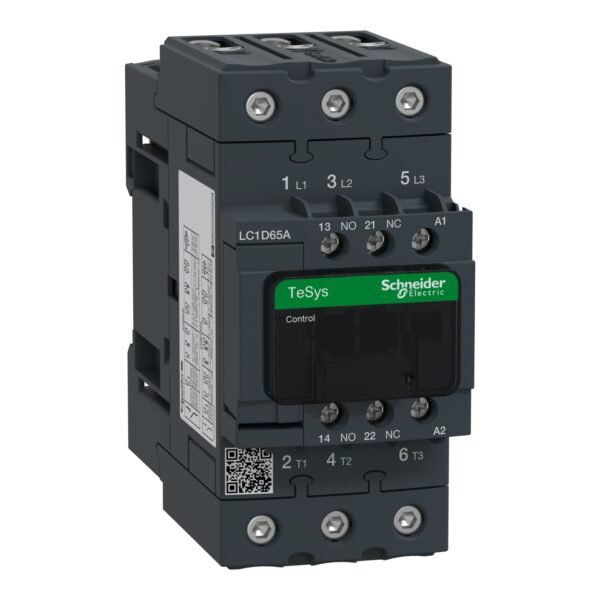
Specifications and ratings
The Schneider LC1D150Q7 Contactor is rated for 150 amps, making it suitable for handling heavy loads in industrial settings. It is designed to operate at voltages up to 600 volts AC, offering reliable performance in diverse applications.
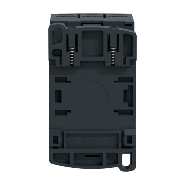
Design and construction
This contactor features a robust construction with high-quality materials, ensuring durability and long-term reliability. It is built to withstand harsh environmental conditions and frequent switching cycles, making it ideal for demanding industrial environments.
Applications of Schneider LC1D150Q7 Contactor
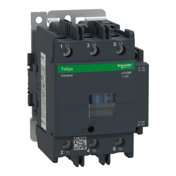
Industrial use cases
The Schneider LC1D150Q7 Contactor is widely used in industrial machinery, such as motor control systems, conveyor belts, and manufacturing equipment. Its high current rating and rugged design make it suitable for heavy-duty applications in factories and production facilities.
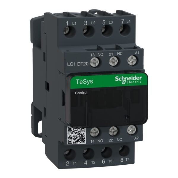
Residential applications
In addition to industrial settings, this contactor can also be used in residential applications, such as controlling the power supply to HVAC systems, water heaters, and electric motors. Its versatility and reliability make it a popular choice for homeowners and contractors alike.
Installation and Wiring Guide
Step-by-step installation process
Installing the Schneider LC1D150Q7 Contactor is straightforward, but it requires careful attention to wiring and safety precautions. Begin by disconnecting power to the circuit and ensuring proper grounding before proceeding with the installation.
Wiring instructions
Refer to the manufacturer’s instructions for detailed wiring diagrams and connection guidelines. Use appropriate wire sizes and terminal connections to ensure reliable performance and compliance with electrical codes and standards.
Maintenance Tips for Schneider LC1D150Q7 Contactor
Regular inspections
To ensure optimal performance and longevity, perform regular inspections of the contactor for signs of wear, corrosion, or damage. Clean the contacts and terminals as needed and replace any worn-out components to prevent malfunctions.
Troubleshooting common issues
If the contactor exhibits unusual behavior or fails to operate correctly, troubleshoot the system to identify and address any underlying issues. Check for loose connections, faulty wiring, or defective components that may affect performance.
Safety Precautions
Importance of safety measures
When working with electrical equipment, always prioritize safety to prevent accidents and injuries. Wear appropriate protective gear and follow proper procedures to minimize the risk of electric shock, burns, or other hazards.
Guidelines for safe usage
Before operating the Schneider LC1D150Q7 Contactor, familiarize yourself with its features and functionality. Follow all safety instructions provided by the manufacturer and avoid overloading the contactor beyond its rated capacity.
Additional information
| brands | Schneider Electric |
|---|


Reviews
There are no reviews yet.