
No products in the cart.
-45%On Sale

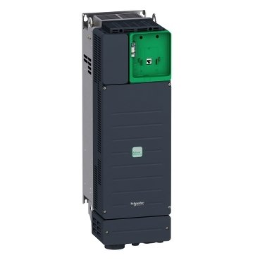
Schneider ATV340D30N4E | Variable speed drive, Altivar Machine ATV340, 30 kW, 400 V, 3 phases, Ethernet
Schneider ATV340D30N4E | Variable speed drive, Altivar Machine ATV340, 30 kW, 400 V, 3 phases, Ethernet
Original price was: EGP 301,822.75.EGP 166,002.50Current price is: EGP 166,002.50.
Description
Schneider ATV340D30N4E: The Pinnacle of Advanced Motor Control
Introduction
In the ever-evolving industrial landscape, the need for precise motor control and energy efficiency has never been greater. The Schneider ATV340D30N4E variable speed drive is engineered to meet these demands. But what sets this drive apart, and how can it elevate your operations?
What is Schneider ATV340D30N4E?
it is an advanced variable speed drive tailored for a wide range of applications. Renowned for its reliability and sophisticated features, it is an indispensable tool for optimizing motor performance and enhancing operational efficiency.
Technical Specifications
Understanding the technical specifications of it is crucial for its effective use. Key aspects include:
- Power Rating: With a 30 kW power rating, it is suitable for larger motors and demanding applications.
- Input and Output Voltage: Operates at an input voltage of 380-480V and provides an output voltage within the same range.
- Frequency Range: Supports a frequency range of 0.1 to 599 Hz, offering extensive flexibility in motor speed control.
Benefits of Using Schneider ATV340D30N4E
it offers numerous benefits, making it a top choice for industrial applications:
- Advanced Motor Control: Ensures precise and smooth motor operation.
- Energy Efficiency: Optimizes performance to reduce energy consumption and lower operational costs.
- Easy Integration: Designed for seamless integration with existing systems, minimizing installation challenges.
Installation and Setup
Installing it is straightforward, though it requires careful attention to detail:
Pre-installation Considerations
Ensure you have all the necessary tools and understand the motor and system requirements where the drive will be installed.
Step-by-Step Installation Guide
- Turn off Power: Always start by shutting down the power to avoid any accidents.
- Mount the Device: Secure the drive in an accessible location.
- Connect Wires: Follow the wiring diagram to connect the device correctly.
- Power Up: Once everything is connected, turn the power back on and verify the installation.
Safety Precautions
Adhere to safety guidelines to prevent electrical hazards during installation.
User Interface and Connectivity
The user interface and connectivity options of it are designed for ease of use:
- Display and Control Features: It features a clear display and intuitive controls for easy operation.
- Connectivity Options: Ensures seamless integration with other industrial control systems and networks.
Applications of Schneider ATV340D30N4E
The versatility of it makes it suitable for various applications:
Industrial Usage
Ideal for manufacturing plants, automation systems, and conveyor belts, ensuring reliable motor control.
Commercial Usage
Perfect for HVAC systems, elevators, and other commercial motor-driven applications.
Specific Use Cases
Suitable for pumps, fans, and other critical processes requiring precise motor speed control.
Additional information
| brands | Schneider Electric |
|---|
Specifications
| Range of product | Altivar Machine ATV340 |
|---|---|
| product or component type | Variable speed drive |
| Product specific application | Machine |
| variant | Standard version |
| mounting mode | Wall mount |
| Communication port protocol | EtherNet/IP Modbus TCP Modbus serial |
| Option card | Communication module, PROFINET Communication module, DeviceNet Communication module, CANopen Communication module, EtherCAT |
| Network number of phases | 3 phases |
| Supply frequency | 50...60 Hz +/- 5 % |
| [Us] rated supply voltage | 380...480 V - 15...10 % |
| Nominal output current | 61.5 A |
| Motor power kW | 37 kW for normal duty 30 kW for heavy duty |
| Motor power hp | 50 hp for normal duty 40 hp for heavy duty |
| EMC filter | Class C3 EMC filter integrated |
| IP degree of protection | IP20 |
| Degree of protection | UL type 1 |
| Discrete input number | 8 |
|---|---|
| Discrete input type | PTI safe torque off: 0…30 kHz, 24 V DC (30 V) DI1...DI5 programmable as pulse input, 24 V DC (30 V), impedance: 3.5 kOhm programmable |
| number of preset speeds | 16 preset speeds |
| Discrete output number | 1.0 |
| Discrete output type | Programmable output DQ1, DQ2 30 V DC 100 mA |
| Analogue input number | 3 |
| Analogue input type | AI1 software-configurable current: 0...20 mA, impedance: 250 Ohm, resolution 12 bits AI1 software-configurable temperature probe or water level sensor AI1 software-configurable voltage: 0...10 V DC, impedance: 31.5 kOhm, resolution 12 bits AI2 software-configurable voltage: - 10...10 V DC, impedance: 31.5 kOhm, resolution 12 bits |
| Analogue output number | 2 |
| Analogue output type | Software-configurable voltage AQ1, AQ2: 0...10 V DC impedance 470 Ohm, resolution 10 bits Software-configurable current AQ1, AQ2: 0...20 mA impedance 500 Ohm, resolution 10 bits |
| Relay output number | 3 |
| Output voltage | <= power supply voltage |
| Relay output type | Relay outputs R1A Relay outputs R1C electrical durability 100000 cycles Relay outputs R2A Relay outputs R2C electrical durability 100000 cycles |
| Maximum switching current | Relay output R1C on resistive load, cos phi = 1: 3 A at 250 V AC Relay output R1C on resistive load, cos phi = 1: 3 A at 30 V DC Relay output R1C on inductive load, cos phi = 0.4 and L/R = 7 ms: 2 A at 250 V AC Relay output R1C on inductive load, cos phi = 0.4 and L/R = 7 ms: 2 A at 30 V DC Relay output R2C on resistive load, cos phi = 1: 5 A at 250 V AC Relay output R2C on resistive load, cos phi = 1: 5 A at 30 V DC Relay output R2C on inductive load, cos phi = 0.4 and L/R = 7 ms: 2 A at 250 V AC Relay output R2C on inductive load, cos phi = 0.4 and L/R = 7 ms: 2 A at 30 V DC |
| Minimum switching current | Relay output R1B: 5 mA at 24 V DC Relay output R2C: 5 mA at 24 V DC |
| Physical interface | 2-wire RS 485 |
| Connector type | 3 RJ45 |
| Method of access | Slave Modbus RTU Slave Modbus TCP |
| Transmission rate | 4.8 kbit/s 9.6 kbit/s 19.2 kbit/s 38.4 kbit/s |
| Transmission frame | RTU |
| Number of addresses | 1…247 |
| Data format | 8 bits, configurable odd, even or no parity |
| Type of polarization | No impedance |
| 4 quadrant operation possible | True |
| Asynchronous motor control profile | Variable torque standard Optimized torque mode Constant torque standard |
| Synchronous motor control profile | Reluctance motor Permanent magnet motor |
| Pollution degree | 2 conforming to IEC 61800-5-1 |
| Maximum output frequency | 0.599 kHz |
| Acceleration and deceleration ramps | Linear adjustable separately from 0.01...9999 s S, U or customized |
| Motor slip compensation | Automatic whatever the load Not available in permanent magnet motor law Adjustable Can be suppressed |
| Switching frequency | 2...16 kHz adjustable 4...16 kHz with derating factor |
| Nominal switching frequency | 4 kHz |
| Braking to standstill | By DC injection |
| Brake chopper integrated | True |
| Line current | 66.2 A at 380 V (normal duty) 57.3 A at 480 V (normal duty) 54.8 A at 380 V (heavy duty) 48.3 A at 480 V (heavy duty) |
| Line current | 66.2 A at 380 V with internal line choke (normal duty) 57.3 A at 480 V with internal line choke (normal duty) 66.2 A at 380 V with internal line choke (heavy duty) 57.3 A at 480 V with internal line choke (heavy duty) 54.8 A 48.3 A |
| Maximum input current | 66.2 A |
| Maximum output voltage | 480 V |
| Apparent power | 47.6 kVA at 480 V (normal duty) 40.2 kVA at 480 V (heavy duty) |
| Maximum transient current | 89.4 A during 60 s (normal duty) 89.4 A during 2 s (normal duty) 92.3 A during 60 s (heavy duty) 92.3 A during 2 s (heavy duty) |
| Electrical connection | Screw terminal, clamping capacity: 35...50 mm² for line side Screw terminal, clamping capacity: 25...50 mm² for DC bus Screw terminal, clamping capacity: 35...50 mm² for motor Screw terminal, clamping capacity: 0.75...1.5 mm² for control |
| Prospective line Isc | 50 kA |
| Base load current at high overload | 61.5 A |
| Base load current at low overload | 74.5 A |
| Power dissipation in W | Natural convection: 77 W at 380 V, switching frequency 4 kHz (heavy duty) Forced convection: 640 W at 380 V, switching frequency 4 kHz (heavy duty) Natural convection: 90 W at 380 V, switching frequency 4 kHz (normal duty) Forced convection: 796 W at 380 V, switching frequency 4 kHz (normal duty) |
| Electrical connection | Line side: screw terminal 35...50 mm²/AWG 3...AWG 1 DC bus: screw terminal 25...50 mm²/AWG 4...AWG 1 Motor: screw terminal 35...50 mm²/AWG 3...AWG 1 Control: screw terminal 0.75...1.5 mm²/AWG 18...AWG 16 |
| With safety function Safely Limited Speed (SLS) | True |
| With safety function Safe brake management (SBC/SBT) | True |
| With safety function Safe Operating Stop (SOS) | False |
| With safety function Safe Position (SP) | False |
| With safety function Safe programmable logic | False |
| With safety function Safe Speed Monitor (SSM) | False |
| With safety function Safe Stop 1 (SS1) | True |
| With sft fct Safe Stop 2 (SS2) | False |
| With safety function Safe torque off (STO) | True |
| With safety function Safely Limited Position (SLP) | False |
| With safety function Safe Direction (SDI) | False |
| Protection type | Thermal protection: motor Safe torque off: motor Motor phase loss: motor Thermal protection: drive Safe torque off: drive Overheating: drive Overcurrent: drive Output overcurrent between motor phase and earth: drive Output overcurrent between motor phases: drive Short-circuit between motor phase and earth: drive Short-circuit between motor phases: drive Motor phase loss: drive DC Bus overvoltage: drive Line supply overvoltage: drive Line supply undervoltage: drive Input supply loss: drive Exceeding limit speed: drive Break on the control circuit: drive |
| Width | 213.0 mm |
| Height | 660.0 mm |
| Depth | 262.0 mm |
| net weight | 27.9 kg |
| Continuous output current | 74.5 A at 4 kHz for normal duty 61.5 A at 4 kHz for heavy duty |
| Operating altitude | <= 4800 m with current derating above 1000m |
|---|---|
| Operating position | Vertical +/- 10 degree |
| Product certifications | UL CSA TÜV EAC CTick |
| marking | CE |
| Standards | IEC 61800-3 IEC 61800-5-1 IEC 60721-3 IEC 61508 IEC 13849-1 UL 618000-5-1 UL 508C IEC 61000-3-12 |
| Maximum THDI | <48 % full load conforming to IEC 61000-3-12 <48 % 80 % load conforming to IEC 61000-3-12 |
| Assembly style | With heat sink |
| Electromagnetic compatibility | Electrostatic discharge immunity test level 3 conforming to IEC 61000-4-2 Radiated radio-frequency electromagnetic field immunity test level 3 conforming to IEC 61000-4-3 Electrical fast transient/burst immunity test level 4 conforming to IEC 61000-4-4 1.2/50 µs - 8/20 µs surge immunity test level 3 conforming to IEC 61000-4-5 Conducted radio-frequency immunity test level 3 conforming to IEC 61000-4-6 |
| Environmental class (during operation) | Class 3C3 according to IEC 60721-3-3 Class 3S3 according to IEC 60721-3-3 |
| Maximum acceleration under shock impact (during operation) | 150 m/s² at 11 ms |
| Maximum acceleration under vibrational stress (during operation) | 10 m/s² at 13...200 Hz |
| Maximum deflection under vibratory load (during operation) | 1.5 mm at 2...13 Hz |
| Permitted relative humidity (during operation) | Class 3K5 according to EN 60721-3 |
| Volume of cooling air | 240.0 m3/h |
| Type of cooling | Forced convection |
| Overvoltage category | Class III |
| Regulation loop | Adjustable PID regulator |
| Noise level | 63.5 dB |
| Pollution degree | 2 |
| Ambient air transport temperature | -40…70 °C |
| Ambient air temperature for operation | -15…50 °C without derating (vertical position) 50…60 °C with derating factor (vertical position) |
| Ambient air temperature for storage | -40…70 °C |
| Isolation | Between power and control terminals |
| Unit Type of Package 1 | PCE |
|---|---|
| Number of Units in Package 1 | 1 |
| Package 1 Height | 51.000 cm |
| Package 1 Width | 84.000 cm |
| Package 1 Length | 34.000 cm |
| Package 1 Weight | 30.000 kg |


Reviews
There are no reviews yet.