
No products in the cart.
-45%On Sale
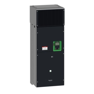
Schneider ATV630C22N4 | variable speed drive ATV630 – 220kW/350HP – 380…480V – IP00
Schneider ATV630C22N4 | variable speed drive ATV630 – 220kW/350HP – 380…480V – IP00
Original price was: EGP 12,801,402.00.EGP 7,040,772.00Current price is: EGP 7,040,772.00.
Description
Introduction
The Schneider ATV630C22N4 is a versatile and powerful variable speed drive designed to optimize industrial processes. Its advanced features and robust design make it an essential tool in various industrial applications, offering both efficiency and reliability.
What is the Schneider ATV630C22N4?
it is part of the Altivar Process 630 range, known for its high performance and energy efficiency. This model stands out due to its flexibility and scalability, making it suitable for a wide range of applications. Compared to other models in the ATV630 series, the ATV630C22N4 offers enhanced features tailored for demanding industrial environments.
Key Features of the Schneider ATV630C22N4
Energy Efficiency
One of the standout features of it is its energy efficiency. It is designed to reduce energy consumption significantly, contributing to lower operational costs and a smaller carbon footprint.
Flexibility and Scalability
it is highly flexible and scalable, allowing it to be adapted for various industrial needs. Its modular design ensures that it can be easily integrated into existing systems and scaled up as needed.
Robust Design
Built to withstand harsh industrial conditions, it features a robust design that ensures longevity and reliability. Its durable construction minimizes downtime and maintenance costs.
Technical Specifications
Power Ratings
The ATV630C22N4 offers a wide range of power ratings to accommodate different applications. This ensures that it can meet the specific needs of various industries.
Input and Output Voltage
This model supports multiple input and output voltage ranges, providing flexibility in different industrial settings.
Frequency Range
The ATV630C22N4 operates within a broad frequency range, making it suitable for various types of machinery and equipment.
Applications of the Schneider ATV630C22N4
Industrial Automation
In industrial automation, the ATV630C22N4 plays a critical role in enhancing the efficiency and performance of automated systems. It ensures precise control and smooth operation of machinery.
HVAC Systems
The ATV630C22N4 is also widely used in HVAC systems, where it helps in optimizing energy use and maintaining consistent performance.
Water and Wastewater Management
In water and wastewater management, the ATV630C22N4 ensures efficient and reliable operation of pumps and other equipment, contributing to effective resource management.
Advantages of Using Schneider ATV630C22N4
Cost Savings
By reducing energy consumption and maintenance costs, the ATV630C22N4 offers significant cost savings over its lifecycle.
Enhanced Operational Efficiency
The precise control and advanced features of the ATV630C22N4 enhance operational efficiency, ensuring smooth and uninterrupted processes.
Reduced Environmental Impact
With its energy-efficient design, the ATV630C22N4 helps reduce the environmental impact of industrial operations, supporting sustainability goals.
Installation and Setup
Pre-Installation Considerations
Before installing the ATV630C22N4, it is important to consider factors such as the installation environment and compatibility with existing systems.
Step-by-Step Installation Guide
- Prepare the installation site.
- Mount the drive securely.
- Connect the electrical wiring according to the manual.
- Configure the drive settings.
Initial Setup and Configuration
After installation, the initial setup involves configuring the drive parameters to match the specific application requirements.
Maintenance and Troubleshooting
Routine Maintenance Tips
Regular maintenance is crucial to ensure the longevity and optimal performance of the ATV630C22N4. This includes periodic inspections and cleaning.
Common Issues and Solutions
Some common issues with the ATV630C22N4 include overheating and communication errors. These can often be resolved through troubleshooting steps provided in the user manual.
Support and Resources
Schneider provides extensive support and resources for the ATV630C22N4, including technical support and online resources.
Energy Management with ATV630C22N4
Energy Monitoring Capabilities
it comes with built-in energy monitoring capabilities, allowing users to track and optimize energy usage.
Integration with Energy Management Systems
This drive can be integrated with broader energy management systems, providing a comprehensive solution for energy efficiency.
Benefits of Energy Management
Effective energy management with it leads to reduced energy costs and enhanced sustainability.
Additional information
| brands | Schneider Electric |
|---|
Specifications
| Range of product | Altivar Process ATV600 |
|---|---|
| Product or component type | Variable speed drive |
| Product specific application | Process and utilities |
| Device short name | ATV630 |
| variant | Standard version |
| product destination | Asynchronous motors Synchronous motors |
| EMC filter | Integrated with 50 m conforming to EN/IEC 61800-3 category C3 |
| IP degree of protection | IP00 conforming to IEC 61800-5-1 IP00 conforming to IEC 60529 IP21 (with kit VW3A9112) conforming to IEC 61800-5-1 IP21 (with kit VW3A9112) conforming to IEC 60529 |
| [Us] rated supply voltage | 380...480 V |
| Type of cooling | Forced convection |
| Supply frequency | 50...60 Hz - 5...5 % |
| [Us] rated supply voltage | 380...480 V - 15...10 % |
| Motor power kW | 160 kW (heavy duty) 220 kW (normal duty) |
| Motor power hp | 350 hp normal duty 250 hp heavy duty |
| Line current | 397 A at 380 V (normal duty) 324 A at 480 V (normal duty) 296 A at 380 V (heavy duty) 246 A at 480 V (heavy duty) |
| Prospective line Isc | 50 kA |
| Apparent power | 247 kVA at 480 V (normal duty) 187 kVA at 480 V (heavy duty) |
| Continuous output current | 302 A at 2.5 kHz for heavy duty 427 A at 2.5 kHz for normal duty |
| Asynchronous motor control profile | Constant torque standard Variable torque standard Optimized torque mode |
| Synchronous motor control profile | Permanent magnet motor Synchronous reluctance motor |
| Speed drive output frequency | 0.1…500 Hz |
| Nominal switching frequency | 2.5 kHz |
| Switching frequency | 2.5...8 kHz with derating factor 2...8 kHz adjustable |
| Safety function | STO (safe torque off) SIL 3 |
| Discrete input logic | 16 preset speeds |
| Communication port protocol | Modbus TCP Ethernet Modbus serial |
| Option card | Slot A: communication module, Profibus DP V1 Slot A: communication module, PROFINET Slot A: communication module, DeviceNet Slot A: communication module, Modbus TCP/EtherNet/IP Slot A: communication module, CANopen daisy chain RJ45 Slot A: communication module, CANopen SUB-D 9 Slot A: communication module, CANopen screw terminals Slot A/slot B: digital and analog I/O extension module Slot A/slot B: output relay extension module Slot A: communication module, Ethernet IP/Modbus TCP/MD-Link Communication module, BACnet MS/TP Communication module, Ethernet Powerlink |
| mounting mode | Wall mount |
|---|---|
| Maximum transient current | 453 A during 60 s (heavy duty) 470 A during 60 s (normal duty) |
| Network number of phases | 3 phases |
| Discrete output number | 0 |
| Discrete output type | Relay outputs R1A, R1B, R1C 250 V AC 3000 mA Relay outputs R1A, R1B, R1C 30 V DC 3000 mA Relay outputs R2A, R2C 250 V AC 5000 mA Relay outputs R2A, R2C 30 V DC 5000 mA Relay outputs R3A, R3C 250 V AC 5000 mA Relay outputs R3A, R3C 30 V DC 5000 mA |
| Output voltage | <= power supply voltage |
| Permissible temporary current boost | 1.1 x In during 60 s (normal duty) 1.5 x In during 60 s (heavy duty) |
| Motor slip compensation | Adjustable Automatic whatever the load Not available in permanent magnet motor law Can be suppressed |
| Acceleration and deceleration ramps | Linear adjustable separately from 0.01...9999 s |
| Physical interface | Ethernet 2-wire RS 485 |
| Braking to standstill | By DC injection |
| Protection type | Thermal protection: motor Safe torque off: motor Motor phase break: motor Thermal protection: drive Safe torque off: drive Overheating: drive Overcurrent between output phases and earth: drive Overload of output voltage: drive Short-circuit protection: drive Motor phase break: drive Overvoltages on the DC bus: drive Line supply overvoltage: drive Line supply undervoltage: drive Line supply phase loss: drive Overspeed: drive Break on the control circuit: drive |
| Transmission rate | 10, 100 Mbits 4800 bps, 9600 bps, 19200 bps, 38.4 Kbps |
| Frequency resolution | Display unit: 0.1 Hz Analog input: 0.012/50 Hz |
| Transmission frame | RTU |
| Electrical connection | Control: removable screw terminals 0.5...1.5 mm²/AWG 20...AWG 16 Line side: screw terminal 2 x 150 mm²/2 x 350 kcmil Motor: screw terminal 2 x 150 mm²/2 x 350 kcmil |
| Connector type | RJ45 (on the remote graphic terminal) for Ethernet/Modbus TCP RJ45 (on the remote graphic terminal) for Modbus serial |
| Data format | 8 bits, configurable odd, even or no parity |
| Type of polarization | No impedance |
| Exchange mode | Half duplex, full duplex, autonegotiation Ethernet/Modbus TCP |
| Number of addresses | 1…247 for Modbus serial |
| Method of access | Slave Modbus TCP |
| Supply | External supply for digital inputs: 24 V DC (19…30 V), <1.25 mA, protection type: overload and short-circuit protection Internal supply for reference potentiometer (1 to 10 kOhm): 10.5 V DC +/- 5 %, <10 mA, protection type: overload and short-circuit protection Internal supply for digital inputs and STO: 24 V DC (21…27 V), <200 mA, protection type: overload and short-circuit protection |
| Local signalling | 3 LEDs for local diagnostic 3 LEDs (dual colour) for embedded communication status 4 LEDs (dual colour) for communication module status 1 LED (red) for presence of voltage |
| Width | 440 mm |
| Height | 1195 mm |
| Depth | 380 mm |
| Net weight | 172 kg |
| Analogue input number | 3 |
| Analogue input type | AI1, AI2, AI3 software-configurable voltage: 0...10 V DC, impedance: 31.5 kOhm, resolution 12 bits AI1, AI2, AI3 software-configurable current: 0...20 mA, impedance: 250 Ohm, resolution 12 bits AI2 voltage analog input: - 10...10 V DC, impedance: 31.5 kOhm, resolution 12 bits |
| Discrete input number | 8 |
| Discrete input type | DI7, DI8 programmable as pulse input: 0…30 kHz, 24 V DC (<= 30 V) |
| Input compatibility | DI1...DI6: discrete input level 1 PLC conforming to EN/IEC 61131-2 DI5, DI6: discrete input level 1 PLC conforming to IEC 65A-68 STOA, STOB: discrete input level 1 PLC conforming to EN/IEC 61131-2 |
| Discrete input logic | Positive logic (source) (DI1...DI8), < 5 V (state 0), > 11 V (state 1) Negative logic (sink) (DI1...DI8), > 16 V (state 0), < 10 V (state 1) |
| Analogue output number | 2 |
| Analogue output type | Software-configurable voltage AQ1, AQ2: 0...10 V DC impedance 470 Ohm, resolution 10 bits Software-configurable current AQ1, AQ2: 0...20 mA, resolution 10 bits Software-configurable current DQ-, DQ+: 30 V DC Software-configurable current DQ-, DQ+: 100 mA |
| Sampling duration | 2 ms +/- 0.5 ms (DI1...DI4) - discrete input 5 ms +/- 1 ms (DI5, DI6) - discrete input 5 ms +/- 0.1 ms (AI1, AI2, AI3) - analog input 10 ms +/- 1 ms (AO1) - analog output |
| Accuracy | +/- 0.6 % AI1, AI2, AI3 for a temperature variation 60 °C analog input +/- 1 % AO1, AO2 for a temperature variation 60 °C analog output |
| Linearity error | AI1, AI2, AI3: +/- 0.15 % of maximum value for analog input AO1, AO2: +/- 0.2 % for analog output |
| Relay output number | 3 |
| Relay output type | Configurable relay logic R1: fault relay NO/NC electrical durability 100000 cycles Configurable relay logic R2: sequence relay NO electrical durability 100000 cycles Configurable relay logic R3: sequence relay NO electrical durability 100000 cycles |
| Refresh time | Relay output (R1, R2, R3): 5 ms (+/- 0.5 ms) |
| Minimum switching current | Relay output R1, R2, R3: 5 mA at 24 V DC |
| Maximum switching current | Relay output R1, R2, R3 on resistive load, cos phi = 1: 3 A at 250 V AC Relay output R1, R2, R3 on resistive load, cos phi = 1: 3 A at 30 V DC Relay output R1, R2, R3 on inductive load, cos phi = 0.4 and L/R = 7 ms: 2 A at 250 V AC Relay output R1, R2, R3 on inductive load, cos phi = 0.4 and L/R = 7 ms: 2 A at 30 V DC |
| Isolation | Between power and control terminals |
| Maximum output frequency | 500 kHz |
| Maximum input current | 397.0 A |
| Variable speed drive application selection | Building - HVAC compressor centrifugal Food and beverage processing other application Mining mineral and metal fan Mining mineral and metal pump Oil and gas fan Water and waste water other application Building - HVAC screw compressor Food and beverage processing pump Food and beverage processing fan Food and beverage processing atomization Oil and gas electro submersible pump (ESP) Oil and gas water injection pump Oil and gas jet fuel pump Oil and gas compressor for refinery Water and waste water centrifuge pump Water and waste water positive displacement pump Water and waste water electro submersible pump (ESP) Water and waste water screw pump Water and waste water lobe compressor Water and waste water screw compressor Water and waste water compressor centrifugal Water and waste water fan Water and waste water conveyor Water and waste water mixer |
| Motor power range AC-3 | 110…220 kW at 380…440 V 3 phases 110…220 kW at 480…500 V 3 phases |
| Quantity per set | 1 |
| enclosure mounting | Wall mounted |
| Insulation resistance | > 1 MOhm 500 V DC for 1 minute to earth |
|---|---|
| Noise level | 66 dB conforming to 86/188/EEC |
| Power dissipation in W | Forced convection: 5030 W Natural convection: 451 W at 380 V, switching frequency 2.5 kHz |
| Volume of cooling air | 860 m3/h |
| Operating position | Vertical +/- 10 degree |
| Maximum THDI | <48 % full load conforming to IEC 61000-3-12 |
| Electromagnetic compatibility | Electrostatic discharge immunity test level 3 conforming to IEC 61000-4-2 Radiated radio-frequency electromagnetic field immunity test level 3 conforming to IEC 61000-4-3 Electrical fast transient/burst immunity test level 4 conforming to IEC 61000-4-4 1.2/50 µs - 8/20 µs surge immunity test level 3 conforming to IEC 61000-4-5 Conducted radio-frequency immunity test level 3 conforming to IEC 61000-4-6 |
| Pollution degree | 2 conforming to EN/IEC 61800-5-1 |
| Vibration resistance | 1.5 mm peak to peak (f= 2…13 Hz) conforming to IEC 60068-2-6 1 gn (f= 13…200 Hz) conforming to IEC 60068-2-6 |
| Shock resistance | 15 gn for 11 ms conforming to IEC 60068-2-27 |
| Relative humidity | 5…95 % without condensation conforming to IEC 60068-2-3 |
| Ambient air temperature for operation | -10…40 °C (without derating) 40…60 °C (with derating factor) |
| ambient air temperature for storage | -25…70 °C |
| Operating altitude | <= 1000 m without derating 1000...3000 m with current derating 1 % per 100 m |
| Product certifications | TÜV CSA UL |
| Marking | CE |
| Standards | UL 508C EN/IEC 61800-3 EN/IEC 61800-3 environment 1 category C2 EN/IEC 61800-3 environment 2 category C3 EN/IEC 61800-5-1 IEC 61000-3-12 IEC 60721-3 IEC 61508 IEC 13849-1 |
| Overvoltage category | III |
| Regulation loop | Adjustable PID regulator |
| Noise level | 73 dB |
| Pollution degree | 2 |
| Unit Type of Package 1 | PCE |
|---|---|
| Number of Units in Package 1 | 1 |
| Package 1 Height | 68.0 cm |
| Package 1 Width | 60.0 cm |
| Package 1 Length | 140.0 cm |
| Package 1 Weight | 180.0 kg |


Reviews
There are no reviews yet.