
No products in the cart.
-46%On Sale
Contactors & Protection Relays, Contactors & Reversing Contactors, Industrial Automation and Control, TeSys K
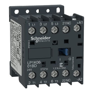
Schneider LP1K1201BD | TeSys K contactor – 3P – AC-3 <= 440 V 12 A – 1 NC aux. – 24 V DC coil
Schneider LP1K1201BD | TeSys K contactor – 3P – AC-3 <= 440 V 12 A – 1 NC aux. – 24 V DC coil
Original price was: EGP 3,751.90.EGP 2,026.00Current price is: EGP 2,026.00.
Description
Schneider LP1K1201BD | TeSys K contactor – 3P – AC-3 <= 440 V 12 A – 1 NC aux. – 24 V DC
coil
Schneider LP1K1201BD: Comprehensive Overview
Introduction
The Schneider LP1K1201BD is an essential component in industrial automation and control systems. This guide provides a detailed look at the LP1K1201BD, including its features, applications, and benefits.
Overview of Schneider Electric
Company Background
Schneider Electric is a leading global provider of energy management and automation solutions. With a reputation for innovation and quality, Schneider Electric plays a crucial role in various industrial and residential sectors.
Commitment to Quality and Innovation
Schneider Electric’s commitment to excellence is reflected in its product offerings. The LP1K1201BD exemplifies the company’s dedication to delivering high-performance and reliable solutions.
Detailed Description of Schneider LP1K1201BD
Product Specifications
it is a contactor designed for use in motor control and switching applications. Key specifications include:
- Type: Contactor
- Current Rating: 12A
- Voltage Rating: Up to 690V AC
- Number of Contacts: 3 Normally Open (NO)
- Coil Voltage: 24V DC
- Mounting Type: DIN Rail Mounting
- Protection Class: IP20
Key Features
- High Switching Capacity: Designed to handle high-current loads efficiently.
- Compact Design: Space-saving design for easy integration into control panels.
- Reliable Performance: Ensures consistent and reliable operation in various conditions.
- Visual Indicators: Equipped with indicators for easy monitoring and status checks.
Applications of Schneider LP1K1201BD
Residential Use
In residential applications, it can be used in home automation systems, controlling various electrical devices and enhancing energy efficiency.
Commercial Use
For commercial environments, including offices and retail spaces, this contactor is ideal for managing lighting systems, HVAC units, and other electrical equipment, improving operational reliability and energy management.
Industrial Use
In industrial settings, it is critical for controlling motors, pumps, and other machinery, ensuring efficient and safe operation in demanding environments.
Installation and Setup
Pre-Installation Considerations
Before installing it, ensure its current and voltage ratings are compatible with your system. Verify that the installation site allows for proper mounting and ventilation.
Step-by-Step Installation Guide
- Prepare the Installation Site: Ensure the area is clean and accessible.
- Mounting: Attach the contactor to the DIN rail using the provided mounting hardware.
- Wiring: Connect the contactor to the electrical system according to the wiring diagram in the manual.
- Configuration: Set up the coil voltage and check connections.
- Testing: Perform a test to ensure proper operation and verify that all indicators are functioning correctly.
Safety Features and Compliance
Built-in Safety Mechanisms
it includes several safety features:
- Overload Protection: Protects against overcurrent conditions to prevent damage.
- Short Circuit Protection: Shields the contactor and connected equipment from short circuits.
- Temperature Compensation: Maintains accurate performance by adjusting for temperature changes.
Compliance with International Standards
The LP1K1201BD meets international standards such as IEC and UL, ensuring high safety and performance standards.
Advantages of Using Schneider LP1K1201BD
Reliability and Durability
The LP1K1201BD is designed for long-term reliability and durability, even in harsh environments, thanks to its robust construction and high-quality materials.
Cost-Effectiveness
The contactor offers a cost-effective solution for motor control and switching applications, providing savings in both installation and maintenance.
Ease of Use
With its user-friendly design and clear indicators, the LP1K1201BD is easy to install and operate, enhancing overall system efficiency.
Additional information
| brands | Schneider Electric |
|---|
Specifications
| Range | TeSys |
|---|---|
| Product or component type | Contactor |
| Device short name | LP1K |
| contactor application | Resistive load Motor control |
| Utilisation category | AC-3 AC-3e AC-1 AC-4 |
|---|---|
| poles description | 3P |
| power pole contact composition | 3 NO |
| [Ue] rated operational voltage | Power circuit: <= 690 V AC <= 400 Hz Signalling circuit: <= 690 V AC <= 400 Hz |
| [Ie] rated operational current | 12 A (at <60 °C) at <= 440 V AC AC-3 for power circuit 12 A (at <60 °C) at <= 440 V AC AC-3e for power circuit 20 A (at <60 °C) at <= 690 V AC AC-1 for power circuit |
| Control circuit type | DC standard |
| [Uc] control circuit voltage | 24 V DC |
| Motor power kW | 3 kW at 220...230 V AC 50/60 Hz AC-3 5.5 kW at 380...415 V AC 50/60 Hz AC-3 5.5 kW at 440 V AC 50/60 Hz AC-3 4 kW at 690 V AC 50/60 Hz AC-3 3 kW at 220...230 V AC 50/60 Hz AC-3e 5.5 kW at 380...415 V AC 50/60 Hz AC-3e 5.5 kW at 440 V AC 50/60 Hz AC-3e 4 kW at 690 V AC 50/60 Hz AC-3e 3 kW at 220...230 V AC 50/60 Hz AC-4 5.5 kW at 380...415 V AC 50/60 Hz AC-4 5.5 kW at 440 V AC 50/60 Hz AC-4 |
| Auxiliary contact composition | 1 NC |
| [Uimp] rated impulse withstand voltage | 8 kV |
| Overvoltage category | III |
| [Ith] conventional free air thermal current | 20 A (at 60 °C) for power circuit 10 A (at 50 °C) for signalling circuit |
| Irms rated making capacity | 144 A AC for power circuit conforming to IEC 60947 110 A AC for signalling circuit conforming to IEC 60947 |
| Rated breaking capacity | 110 A at 440 V conforming to IEC 60947 80 A at 500 V conforming to IEC 60947 70 A at 660...690 V conforming to IEC 60947 |
| [Icw] rated short-time withstand current | 115 A 50 °C - 1 s for power circuit 105 A 50 °C - 5 s for power circuit 100 A 50 °C - 10 s for power circuit 75 A 50 °C - 30 s for power circuit 55 A 50 °C - 1 min for power circuit 50 A 50 °C - 3 min for power circuit 25 A 50 °C - >= 15 min for power circuit 80 A - 1 s for signalling circuit 90 A - 500 ms for signalling circuit 110 A - 100 ms for signalling circuit |
| Associated fuse rating | 25 A gG at <= 440 V for power circuit 25 A aM for power circuit 10 A gG for signalling circuit conforming to IEC 60947 10 A gG for signalling circuit conforming to VDE 0660 |
| Average impedance | 3 mOhm - Ith 20 A 50 Hz for power circuit |
| [Ui] rated insulation voltage | Power circuit: 600 V conforming to UL 508 Power circuit: 690 V conforming to IEC 60947-4-1 Signalling circuit: 690 V conforming to IEC 60947-4-1 Signalling circuit: 690 V conforming to IEC 60947-5-1 Signalling circuit: 600 V conforming to UL 508 Power circuit: 600 V conforming to CSA C22.2 No 14 Signalling circuit: 600 V conforming to CSA C22.2 No 14 |
| Insulation resistance | > 10 MOhm for signalling circuit |
| Inrush power in W | 3 W (at 20 °C) |
| Hold-in power consumption in W | 3 W at 20 °C |
| Heat dissipation | 1.3 W |
| Control circuit voltage limits | Operational: 0.8...1.15 Uc (at <50 °C) Drop-out: >= 0.10 Uc (at <50 °C) |
| Connections - terminals | Screw clamp terminals 1 cable(s) 1.5…4 mm²solid Screw clamp terminals 1 cable(s) 0.75…4 mm²flexible without cable end Screw clamp terminals 1 cable(s) 0.34…2.5 mm²flexible with cable end Screw clamp terminals 2 cable(s) 1.5…4 mm²solid Screw clamp terminals 2 cable(s) 0.75…4 mm²flexible without cable end Screw clamp terminals 2 cable(s) 0.34…1.5 mm²flexible with cable end Power circuit: screw clamp terminals 2 cable(s) 1.5 mm²flexible with cable end |
| Maximum operating rate | 3600 cyc/h |
| Auxiliary contacts type | type instantaneous 1 NC |
| Minimum switching current | 5 mA for signalling circuit |
| Minimum switching voltage | 17 V for signalling circuit |
| Mounting support | Rail Plate |
| Tightening torque | 0.8…1.3 N.m - on screw clamp terminals Philips No 2 0.8…1.3 N.m - on screw clamp terminals flat Ø 6 mm 0.8…1.3 N.m - on screw clamp terminals pozidriv No 2 |
| Operating time | 30...40 ms coil energisation and NO closing 10 ms coil de-energisation and NO opening |
| Safety reliability level | B10d = 1369863 cycles contactor with nominal load conforming to EN/ISO 13849-1 B10d = 20000000 cycles contactor with mechanical load conforming to EN/ISO 13849-1 |
| Mechanical durability | 10 Mcycles |
| Electrical durability | 1.3 Mcycles 12 A AC-3 at Ue <= 440 V 1.3 Mcycles 12 A AC-3e at Ue <= 440 V 0.3 Mcycles 20 A AC-1 at Ue <= 690 V 0.02 Mcycles 72 A AC-4 at Ue <= 440 V |
| Height | 58 mm |
| Width | 45 mm |
| Depth | 57 mm |
| Net weight | 0.225 kg |
| Standards | EN/IEC 60947-4-1 EN/IEC 60947-5-1 UL 60947-4-1 UL 60947-5-1 CSA C22.2 No 60947-4-1 CSA C22.2 No 60947-5-1 GB/T 14048.4 |
|---|---|
| Product certifications | CB Scheme CCC UL CSA EAC CE UKCA |
| IP degree of protection | IP2X |
| Ambient air temperature for operation | -25…50 °C |
| Ambient air temperature for storage | -50…80 °C |
| Permissible ambient air temperature around the device | -40…70 °C at Uc |
| Operating altitude | 2000 m without derating |
| Flame retardance | V1 conforming to UL 94 Requirement 2 conforming to NF F 16-101 Requirement 2 conforming to NF F 16-102 |
| Unit Type of Package 1 | PCE |
|---|---|
| Number of Units in Package 1 | 1 |
| Package 1 Height | 5.000 cm |
| Package 1 Width | 6.000 cm |
| Package 1 Length | 6.500 cm |
| Package 1 Weight | 221.000 g |
| Unit Type of Package 2 | S02 |
| Number of Units in Package 2 | 40 |
| Package 2 Height | 15.000 cm |
| Package 2 Width | 30.000 cm |
| Package 2 Length | 40.000 cm |
| Package 2 Weight | 9.101 kg |
| Unit Type of Package 3 | P06 |
| Number of Units in Package 3 | 640 |
| Package 3 Height | 75.000 cm |
| Package 3 Width | 80.000 cm |
| Package 3 Length | 60.000 cm |
| Package 3 Weight | 153.616 kg |
| Warranty | 18 months |
|---|


Reviews
There are no reviews yet.