
No products in the cart.
-42%On Sale
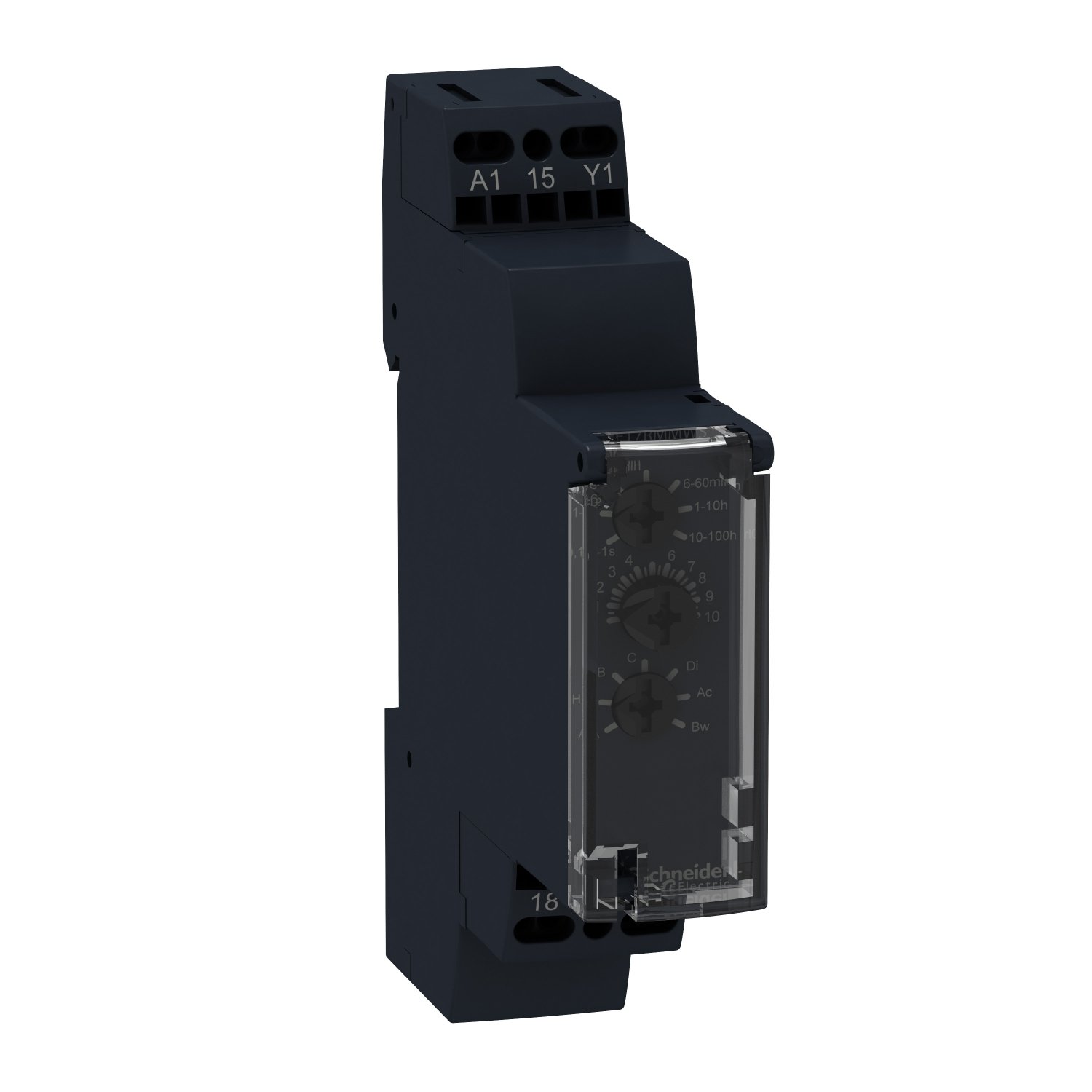
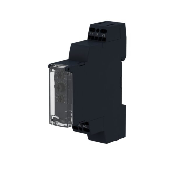
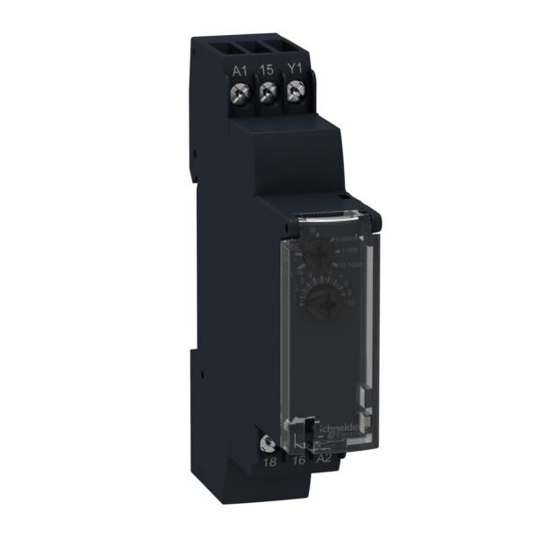
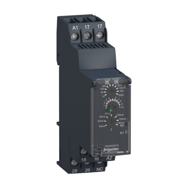
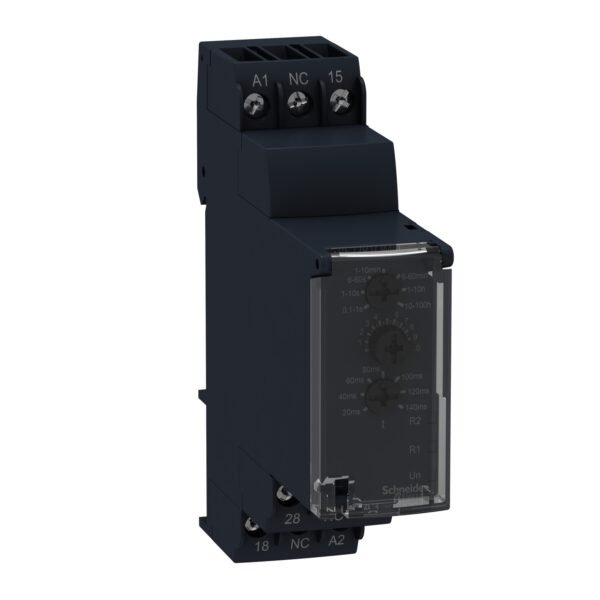
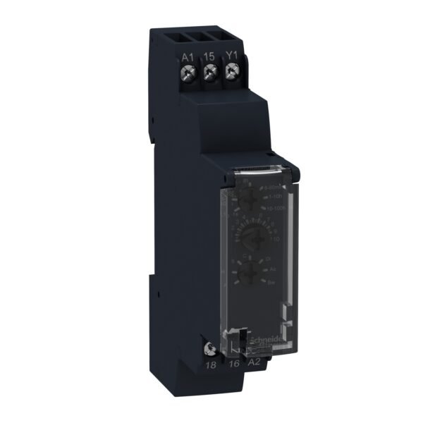
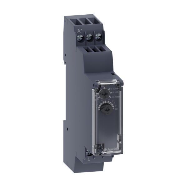
Schneider RE17RMJU | Time delay relay 10 functions – 1 s..100 h – 12 V AC/DC – 1 OC
Original price was: EGP 31,832.00.EGP 18,463.00Current price is: EGP 18,463.00.
Description
Schneider RE17RMJU | Time delay relay 10 functions – 1 s..100 h – 12 V AC/DC – 1 OC
Introduction Time delay relays play a crucial role in various industrial and commercial applications, offering precise control over timing functions. Understanding their features and applications can enhance operational efficiency and safety in electrical systems.
Functions Time delay relays like the Schneider RE17RMJU are designed with 10 key functions, ranging from 1 second to 100 hours. These functions include delay on, delay off, interval, pulse shaping, and more. Each function serves specific timing needs in different scenarios.
Specifications The Schneider RE17RMJU time delay relay operates at 12 V AC/DC and offers versatile timing ranges from 1 second to 100 hours. It features 1 open contact (OC) for switching applications, making it suitable for a wide range of control tasks.
Applications These relays find extensive use in industrial automation, HVAC systems, lighting controls, motor controls, and process timing applications. Their ability to provide precise timing functions ensures seamless operation and optimized performance in diverse settings.
Installation Installing a time delay relay like the Schneider RE17RMJU involves several steps. Begin by identifying the appropriate mounting location and ensuring proper electrical connections. Follow manufacturer guidelines and safety protocols during installation to avoid any mishaps.
Testing After installation, it’s crucial to test the relay to verify its functionality and timing accuracy. Use a multimeter or testing device to check the relay’s response to different input signals and time settings. Adjustments may be necessary to fine-tune the relay for specific requirements.
Maintenance Regular maintenance is key to ensuring the longevity and reliability of time delay relays. Keep the relay clean and free from dust or debris that could affect its performance. Periodic inspections and testing can help detect any issues early on and prevent downtime.
Conclusion Time delay relays like the Schneider RE17RMJU offer precise timing control essential for various industrial and commercial operations. Understanding their functions, specifications, and applications can help businesses improve efficiency and streamline processes.
FAQs
- What is a time delay relay used for? A time delay relay is used to control the timing of electrical processes, providing delays between the initiation of an action and its response.
- How do I choose the right time delay relay for my application? Consider factors such as voltage requirements, timing range, contact type, and specific functions needed for your application to choose the right time delay relay.
- Can time delay relays be used in automotive applications? Yes, time delay relays find applications in automotive systems for functions like delayed lighting, wiper control, and more.
- Are time delay relays user-programmable? Some time delay relays offer programmable features, allowing users to customize timing parameters based on their requirements.
- What safety precautions should I take when working with time delay relays? Always follow manufacturer instructions, disconnect power before installation or maintenance, and use proper protective gear to ensure safety when working with electrical components.
Additional information
| brands | Schneider Electric |
|---|


Reviews
There are no reviews yet.