
No products in the cart.
-45%On Sale
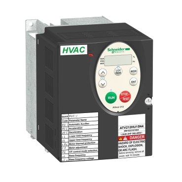
Schneider ATV212HU15N4 | variable speed drive, Altivar 212, 1.5kW, 2hp, 480V, 3 phases, with EMC, IP21
Schneider ATV212HU15N4 | variable speed drive, Altivar 212, 1.5kW, 2hp, 480V, 3 phases, with EMC, IP21
Original price was: EGP 49,182.34.EGP 27,050.28Current price is: EGP 27,050.28.
Description
Schneider ATV212HU15N4: The Ultimate Guide
Introduction
When it comes to efficient motor control in industrial applications, the Schneider ATV212HU15N4 stands out as a reliable and advanced solution. Understanding its features, benefits, and applications can significantly enhance your operational efficiency. This article aims to provide an in-depth look at it, from its key specifications to practical tips for installation and use.
Understanding the Schneider ATV212HU15N4
What is the Schneider ATV212HU15N4?
it is a variable frequency drive (VFD) designed to optimize the performance of HVAC systems and other industrial applications. It provides precise motor control, enhancing the performance and efficiency of your machinery.
Key Features and Specifications
- Power Rating: 15 kW (20 HP)
- Input Voltage: 380-480V, 3-phase
- Output Frequency: 0.5 to 200 Hz
- Control Type: Vector control with sensorless vector capability
- Protection: IP20 enclosure, overcurrent, overvoltage, and thermal protection
Benefits
- Energy Efficiency: Reduces energy consumption by optimizing motor speed.
- Ease of Use: User-friendly interface and simple configuration.
- Reliability: Robust design ensures long-term performance.
- Versatility: Suitable for a wide range of applications.
Applications of the Schneider ATV212HU15N4
Common Industries and Use Cases
it is commonly used in:
- HVAC Systems: Ensuring optimal performance and energy efficiency.
- Pumps and Fans: Controlling speed for better process management.
- Conveyors: Improving operational efficiency in manufacturing.
- Water Treatment Facilities: Optimizing pump operation to conserve energy.
Real-World Examples of Implementation
- Manufacturing Plants: Enhancing production line efficiency.
- Commercial Buildings: Managing HVAC systems for better climate control.
- Agricultural Operations: Controlling irrigation systems for better crop management.
Advantages in Specific Applications
- Precision Control: Achieving desired performance in various processes.
- Cost Savings: Lowering energy bills and maintenance costs.
- Improved Durability: Extending the lifespan of your equipment.
Installation and Setup
Pre-installation Considerations
- Verify Electrical Specifications: Ensure compatibility with your power supply.
- Check Environmental Conditions: Install in a clean, dry, and well-ventilated area.
Step-by-Step Installation Guide
- Mount the VFD: Securely mount it on a stable surface.
- Connect the Power Supply: Follow the wiring diagram to connect to the power source.
- Wire the Motor: Connect the motor terminals to the VFD outputs.
- Configure the Settings: Use the interface to set initial parameters.
Initial Setup and Configuration
- Parameter Setting: Configure parameters like motor voltage, current, and frequency.
- Test Run: Perform a test run to ensure proper operation.
Operating the Schneider ATV212HU15N4
Basic Operation Principles
- Start/Stop Control: Use the interface to start and stop the motor.
- Speed Adjustment: Adjust motor speed using the control panel.
User Interface and Controls
- LCD Display: Provides real-time data on motor performance.
- Keypad: Allows for easy parameter adjustments.
Tips for Efficient Operation
- Regular Monitoring: Keep an eye on performance metrics.
- Optimal Settings: Fine-tune settings for your specific application.
Maintenance and Troubleshooting
Regular Maintenance Practices
- Routine Inspections: Check for dust buildup and clean regularly.
- Firmware Updates: Ensure the VFD firmware is up-to-date.
Common Issues and Their Solutions
- Overheating: Ensure proper ventilation and reduce load if necessary.
- Unexpected Shutdowns: Check for electrical faults or parameter errors.
When to Seek Professional Help
- Complex Issues: If troubleshooting doesn’t resolve the problem, consult a professional.
- Major Repairs: For significant damage, professional repair is recommended.
Advanced Features and Customization
Overview of Advanced Functionalities
- Programmable Logic: Customize operations with built-in programming options.
- Remote Monitoring: Integrate with supervisory systems for remote monitoring.
Customization Options
- User-defined Parameters: Tailor settings to your specific needs.
- Interface Options: Choose between different user interfaces for control.
Integrating with Other Systems
- Communication Protocols: Supports Modbus and other protocols for seamless integration.
- Automation Systems: Compatible with various automation and control systems.
Energy Efficiency and Cost Savings
How the ATV212HU15N4 Enhances Energy Efficiency
- Variable Speed Control: Matches motor speed to the actual load requirement.
- Reduced Power Consumption: Lowers energy usage during low-demand periods.
Cost-saving Benefits
- Lower Utility Bills: Reduced energy consumption translates to savings.
- Extended Equipment Life: Proper motor control reduces wear and tear.
Environmental Impact
- Reduced Carbon Footprint: Lower energy consumption helps in reducing greenhouse gas emissions.
- Sustainable Operations: Supports your sustainability goals.
Additional information
| brands | Schneider Electric |
|---|
Specifications
| Device short name | ATV212 |
|---|---|
| product destination | Asynchronous motors |
| Phase | 3 phase |
| Motor power kW | 1.5 kW |
| Maximum Horse Power Rating | 2 hp |
| Supply voltage limits | 323…528 V |
| Supply frequency | 50...60 Hz - 5...5 % |
| Line current | 2.5 A 480 V 3.2 A 380 V |
| Range of Product | Altivar 212 |
| Product or Component Type | Variable speed drive |
| Product Specific Application | Pumps and fans in HVAC |
| Communication Port Protocol | APOGEE FLN BACnet Modbus LonWorks METASYS N2 |
| [Us] rated supply voltage | 380...480 V - 15...10 % |
| EMC filter | Class C2 EMC filter integrated |
| IP degree of protection | IP21 |
| Apparent power | 2.8 kVA 380 V |
|---|---|
| Continuous output current | 3.7 A 380 V 3.7 A 460 V |
| Maximum transient current | 4 A 60 s |
| Speed drive output frequency | 0.5…200 Hz |
| Speed range | 1…10 |
| Speed accuracy | +/- 10 % of nominal slip 0.2 Tn to Tn |
| Local signalling | For DC bus energized 1 LED (red) |
| Output voltage | <= power supply voltage |
| Isolation | Electrical between power and control |
| Type of cable | Without mounting kit 1 IEC cable 113.0000000000 °F (45 °C), copper 90 °C / XLPE/EPR Without mounting kit 1 IEC cable 113.0000000000 °F (45 °C), copper 70 °C / PVC With UL Type 1 kit 3 UL 508 cable 104.0000000000 °F (40 °C), copper 75 °C / PVC |
| Electrical connection | VIA, VIB, FM, FLA, FLB, FLC, RY, RC, F, R, RES terminal 0.004 in² (2.5 mm²) / AWG 14 L1/R, L2/S, L3/T terminal 0.009 in² (6 mm²) / AWG 10 |
| Tightening torque | 11.5 lbf.in (1.3 N.m), 11.5 lb.in L1/R, L2/S, L3/T) 5.3 lbf.in (0.6 N.m) VIA, VIB, FM, FLA, FLB, FLC, RY, RC, F, R, RES) |
| Supply | Internal supply for reference potentiometer (1 to 10 kOhm) 10.5 V DC +/- 5 %, <10 A overload and short-circuit protection Internal supply 24 V DC 21…27 V), <200 A overload and short-circuit protection |
| Sampling duration | 2 ms +/- 0.5 ms F discrete 2 ms +/- 0.5 ms R discrete 2 ms +/- 0.5 ms RES discrete 3.5 ms +/- 0.5 ms VIA analog 22 ms +/- 0.5 ms VIB analog |
| Response time | FM 2 ms +/- 0.5 ms analog FLA, FLC 7 ms +/- 0.5 ms discrete FLB, FLC 7 ms +/- 0.5 ms discrete RY, RC 7 ms +/- 0.5 ms discrete |
| Accuracy | +/- 0.6 % VIA) for a temperature variation 60 °C +/- 0.6 % VIB) for a temperature variation 60 °C +/- 1 % FM) for a temperature variation 60 °C |
| Linearity error | VIA +/- 0.15 % of maximum value input VIB +/- 0.15 % of maximum value input FM +/- 0.2 % output |
| Analogue output type | FM switch-configurable voltage 0...10 V DC 7620 Ohm 10 bits FM switch-configurable current 0...20 mA 970 Ohm 10 bits |
| Discrete output type | Configurable relay logic FLA, FLC) NO - 100000 cycles Configurable relay logic FLB, FLC) NC - 100000 cycles Configurable relay logic RY, RC) NO - 100000 cycles |
| Minimum switching current | 3 mA 24 V DC configurable relay logic |
| Maximum switching current | 5 A 250 V AC resistive cos phi = 1 L/R = 0 ms FL, R) 5 A 30 V DC resistive cos phi = 1 L/R = 0 ms FL, R) 2 A 250 V AC inductive cos phi = 0.4 L/R = 7 ms FL, R) 2 A 30 V DC inductive cos phi = 0.4 L/R = 7 ms FL, R) |
| Discrete input type | F programmable 24 V DC level 1 PLC 4700 Ohm R programmable 24 V DC level 1 PLC 4700 Ohm RES programmable 24 V DC level 1 PLC 4700 Ohm |
| Discrete input logic | Positive logic (source) F, R, RES), <= 5 V, >= 11 V Negative logic (sink) F, R, RES), >= 16 V, <= 10 V |
| Dielectric strength | 3535 V DC between earth and power terminals 5092 V DC between control and power terminals |
| Insulation resistance | >= 1 mOhm 500 V DC for 1 minute |
| Frequency resolution | Display unit 0.1 Hz Analog input 0.024/50 Hz |
| communication service | Read device identification (43) Time out setting from 0.1 to 100 s Monitoring inhibitable Write single register (06) Read holding registers (03) 2 words maximum Write multiple registers (16) 2 words maximum |
| Option card | Communication card LonWorks |
| Power dissipation in W | 78 W |
| Air flow | 7132.8 Gal/hr(US) (27 m3/h) |
| Functionality | Mid |
| Specific application | HVAC |
| Variable speed drive application selection | Building - HVAC compressor for scroll Building - HVAC fan Building - HVAC pump |
| Motor power range AC-3 | 1.1…2 kW 380…440 V 3 phase 1.1…2 kW 480…500 V 3 phase |
| Motor starter type | Variable speed drive |
| Discrete output number | 2 |
| Analogue input number | 2 |
| Analogue input type | VIA switch-configurable voltage 0...10 V DC 24 V max 30000 Ohm 10 bits VIB configurable voltage 0...10 V DC 24 V max 30000 Ohm 10 bits VIB configurable PTC probe 0...6 probes 1500 Ohm VIA switch-configurable current 0...20 mA 250 Ohm 10 bits |
| Analogue output number | 1 |
| Physical interface | 2-wire RS 485 |
| Connector Type | 1 open style 1 RJ45 |
| Transmission Rate | 9600 bps or 19200 bps |
| Transmission frame | RTU |
| Number of addresses | 1…247 |
| Data format | 8 bits, 1 stop, odd even or no configurable parity |
| Type of polarization | No impedance |
| Asynchronous motor control profile | Voltage/frequency ratio - Energy Saving, quadratic U/f Voltage/frequency ratio, 5 points Voltage/frequency ratio, automatic IR compensation (U/f + automatic Uo) Voltage/frequency ratio, 2 points Flux vector control without sensor, standard |
| Torque accuracy | +/- 15 % |
| Transient overtorque | 120 % of nominal motor torque +/- 10 % 60 s |
| Acceleration and deceleration ramps | Linear adjustable separately from 0.01 to 3200 s Automatic based on the load |
| Motor slip compensation | Adjustable Not available in voltage/frequency ratio motor control Automatic whatever the load |
| Switching frequency | 6...16 kHz adjustable 12...16 kHz with derating factor |
| Nominal switching frequency | 12 kHz |
| Braking to standstill | By DC injection |
| Network Frequency | 47.5...63 Hz |
| Prospective line Isc | 5 kA |
| Protection type | Overheating protection drive Thermal power stage drive Short-circuit between motor phases drive Input phase breaks drive Overcurrent between output phases and earth drive Overvoltages on the DC bus drive Break on the control circuit drive Against exceeding limit speed drive Line supply overvoltage and undervoltage drive Line supply undervoltage drive Against input phase loss drive Thermal protection motor Motor phase break motor With PTC probes motor |
| Width | 4.2 in (107 mm) |
| Height | 5.6 in (143 mm) |
| Depth | 5.9 in (150 mm) |
| Net Weight | 4.4 lb(US) (2 kg) |
| Pollution degree | 2 IEC 61800-5-1 |
|---|---|
| IP degree of protection | IP20 on upper part without blanking plate on cover IEC 61800-5-1 IP20 on upper part without blanking plate on cover IEC 60529 IP21 IEC 61800-5-1 IP21 IEC 60529 IP41 on upper part IEC 61800-5-1 IP41 on upper part IEC 60529 |
| Vibration resistance | 1.5 mm 3…13 Hz)IEC 60068-2-6 1 gn 13…200 Hz)EN/IEC 60068-2-8 |
| Shock resistance | 15 gn 11 ms IEC 60068-2-27 |
| Environmental characteristic | Classes 3C1 IEC 60721-3-3 Classes 3S2 IEC 60721-3-3 |
| Noise level | 51 dB 86/188/EEC |
| Operating altitude | 3280.84...9842.52 ft (1000...3000 m) limited to 2000 m for the Corner Grounded distribution network with current derating 1 % per 100 m <= 3280.84 ft (1000 m) without derating |
| Relative humidity | 5…95 % without condensation IEC 60068-2-3 5…95 % without dripping water IEC 60068-2-3 |
| Ambient air temperature for operation | 14.0000000000…104.0000000000 °F (-10…40 °C) without derating) 104.0000000000…122.0000000000 °F (40…50 °C) with derating factor) |
| Operating position | Vertical +/- 10 degree |
| Product Certifications | UL NOM 117 C-tick CSA |
| Marking | CE |
| Standards | EN 55011 class A group 1 IEC 61800-3 environments 2 category C1 EN 61800-3 category C3 IEC 61800-3 IEC 61800-3 environments 2 category C2 IEC 61800-3 environments 2 category C1 IEC 61800-3 environments 1 category C3 UL Type 1 IEC 61800-3 environments 2 category C3 IEC 61800-3 environments 1 category C2 IEC 61800-3 environments 1 category C3 IEC 61800-3 IEC 61800-3 environments 1 category C2 IEC 61800-3 environments 2 category C3 IEC 61800-3 environments 1 category C1 IEC 61800-5-1 IEC 61800-3 category C3 IEC 61800-3 category C2 IEC 61800-5-1 IEC 61800-3 category C2 IEC 61800-3 environments 1 category C1 IEC 61800-3 environments 2 category C2 |
| Assembly style | With heat sink |
| Electromagnetic compatibility | Electrostatic discharge immunity test level 3 IEC 61000-4-2 Radiated radio-frequency electromagnetic field immunity test level 3 IEC 61000-4-3 Electrical fast transient/burst immunity test level 4 IEC 61000-4-4 1.2/50 µs - 8/20 µs surge immunity test level 3 IEC 61000-4-5 Conducted radio-frequency immunity test level 3 IEC 61000-4-6 Voltage dips and interruptions immunity test IEC 61000-4-11 |
| Regulation loop | Adjustable PI regulator |
| Ambient Air Temperature for Storage | -13.0000000000…158.0000000000 °F (-25…70 °C) |
| Category | US1CP4D22157 |
|---|---|
| Discount Schedule | CP4D |
| GTIN | 3606480322457 |
| Returnability | Yes |
| Country of origin | ID |
| Unit Type of Package 1 | PCE |
|---|---|
| Number of Units in Package 1 | 1 |
| Package 1 Height | 6.890 in (17.500 cm) |
| Package 1 Width | 6.811 in (17.300 cm) |
| Package 1 Length | 8.071 in (20.500 cm) |
| Package 1 Weight | 4.359 lb(US) (1.977 kg) |
| Unit Type of Package 2 | S06 |
| Number of Units in Package 2 | 27 |
| Package 2 Height | 29.528 in (75.000 cm) |
| Package 2 Width | 23.622 in (60.000 cm) |
| Package 2 Length | 31.496 in (80.000 cm) |
| Package 2 Weight | 143.722 lb(US) (65.191 kg) |
| Warranty | 18 months |
|---|


Reviews
There are no reviews yet.